Photograph
Overall views, hinge lines, horn positions, tailwheel hardware, stabilizer attachment, fin support, control exits, and damaged joints.
L-4 Restoration · Chapter 05
The damaged tail is not repaired by building around uncertainty. The fuselage is first held straight and true, then the tailpost, stabilizer platform, fin support, adjoining bays, and complete empennage are rebuilt from known geometry.
This is the first major physical reconstruction phase. When it is complete, the aircraft must have a documented centerline, reliable tail structure, new horizontal and vertical surfaces, renewed controls, and an inspectable path from the servos to every hinge line.
Empennage evidence
The received tail remains useful as a physical reference while the Balsa USA drawing controls the rebuilt structure and hinge relationships.
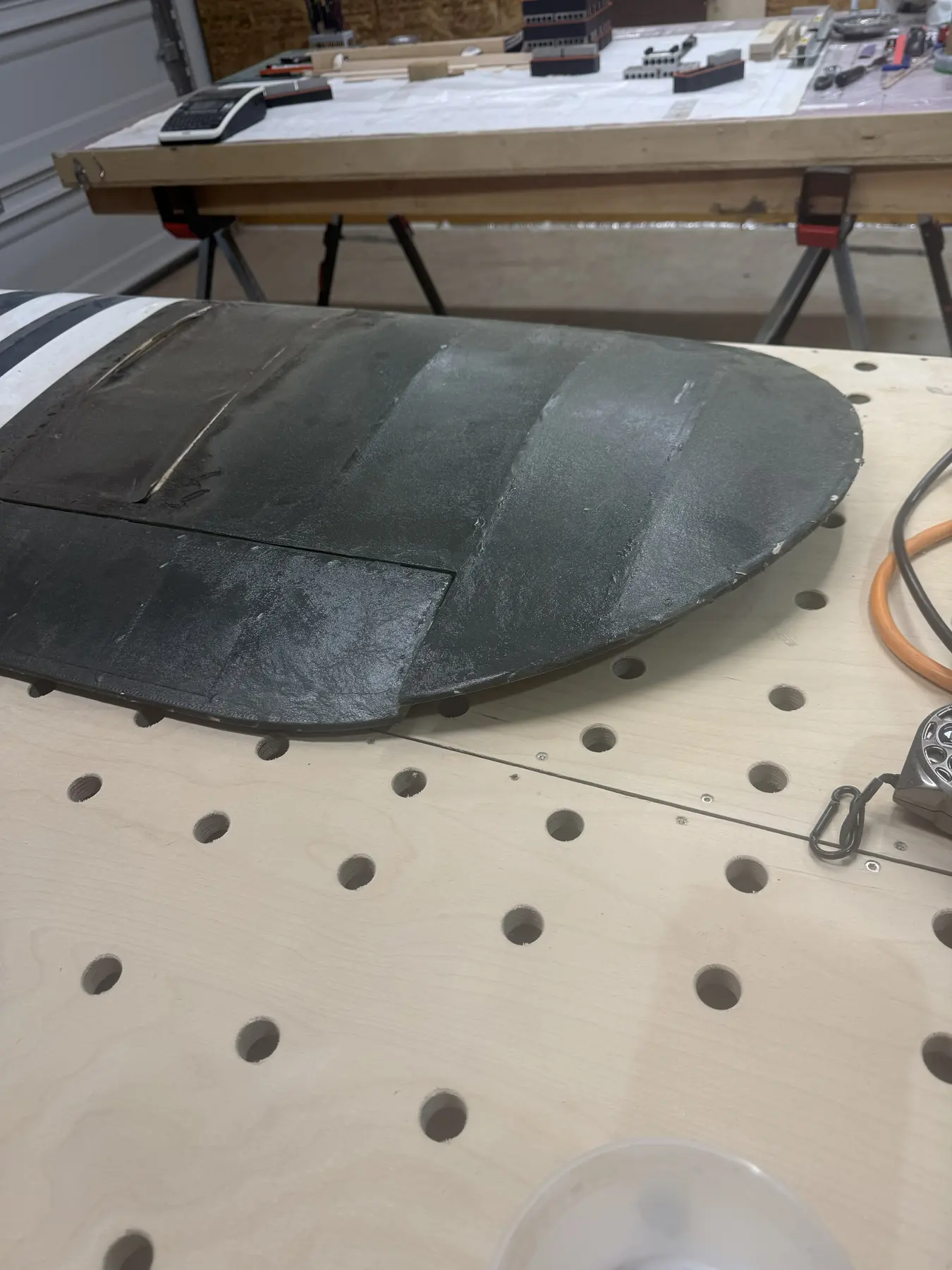
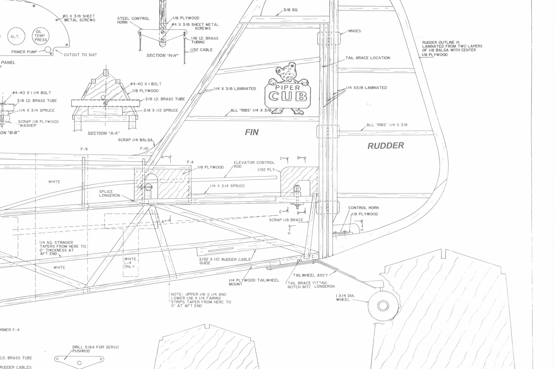
Received Condition
The original stabilizer, elevators, fin, rudder, tailpost area, and damaged adjoining structure are retained as evidence long enough to record outlines, hinge locations, control relationships, hardware positions, and the original builder's intent.
The empennage itself is a complete new build. Weak, distorted, or previously repaired tail surfaces are not patched merely to preserve old material. Their value is as dimensional and configuration evidence.
Before Disassembly
Overall views, hinge lines, horn positions, tailwheel hardware, stabilizer attachment, fin support, control exits, and damaged joints.
Surface spans and chords, hinge spacing, tailpost width, platform height, incidence references, control-horn offsets, and cable exits.
Left, right, top, bottom, forward, aft, original location, orientation, and relationship to the Balsa USA plans.
Jigging and Datum
The fuselage is supported so the centerline, cabin reference, firewall, wing relationship, rear longerons, stabilizer station, and tailpost can be checked together. A new tail built onto a twisted fuselage would only make the error permanent.
Balsa USA plans control reconstructed geometry. The existing airframe records how this model was built and what relationships already exist. Historical references guide visible appearance where the plans and model do not answer a scale-detail question.
Alignment References
Rear Fuselage Reconstruction
Damaged longerons, uprights, diagonals, cross-members, gussets, and tail-support members are removed only to planned boundaries in sound material. New members match the required geometry and grain direction and extend far enough forward to create reliable structural continuity.
The repair is not judged only by whether the tail looks straight. The rear fuselage must resist bending, torsion, tailwheel loads, control loads, covering tension, transport handling, and repeated service access.
Structural Sequence
Identify the last unquestionably sound bays, mark removal limits, and record every original relationship before cutting.
Match left and right geometry, longeron continuity, upright spacing, diagonals, and cross-members while the fuselage remains jigged.
Add tailpost, platforms, gussets, supports, and local reinforcements only after centerline, width, taper, and verticality are verified.
Tail-to-firewall verification after structural repair
The photographs preserve the verification step as part of the restoration record—not merely what was repaired, but how the repaired airframe was checked before moving on.
Structural repair was only part of the job. Before the restoration moved forward, the repaired fuselage was checked for straightness using a simple physical reference.
A taut kite string was secured at the tail and carried forward along the fuselage, passing around the firewall area just behind where the cowl attaches. With the structure still exposed, that continuous string line could be viewed from several positions and compared against the fuselage structure.
This tail-to-firewall string-line check provided a straightforward visual reference for detecting unwanted bow or obvious alignment problems before additional restoration work began covering the structure.
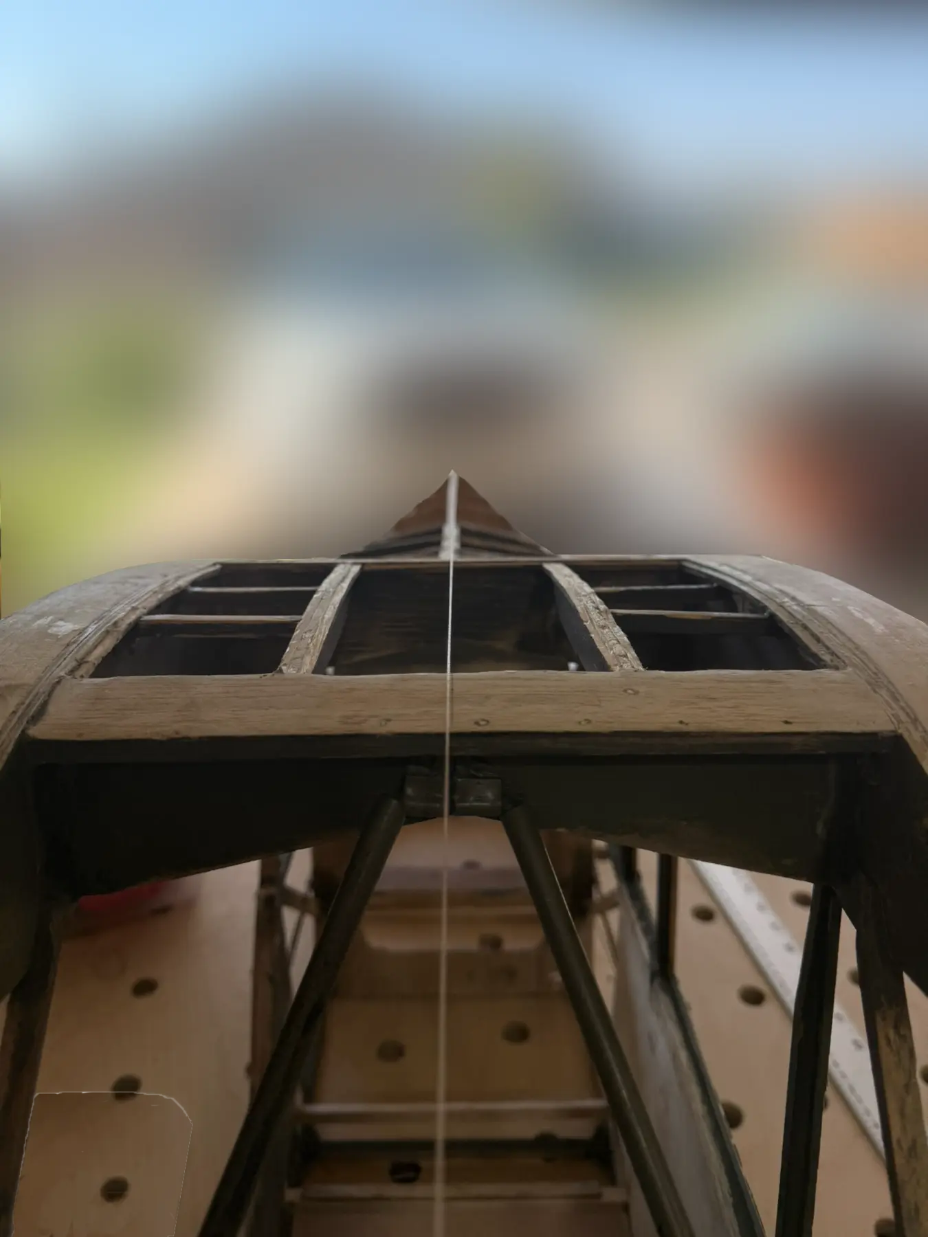
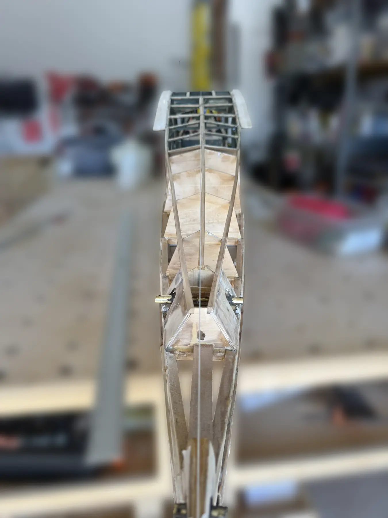
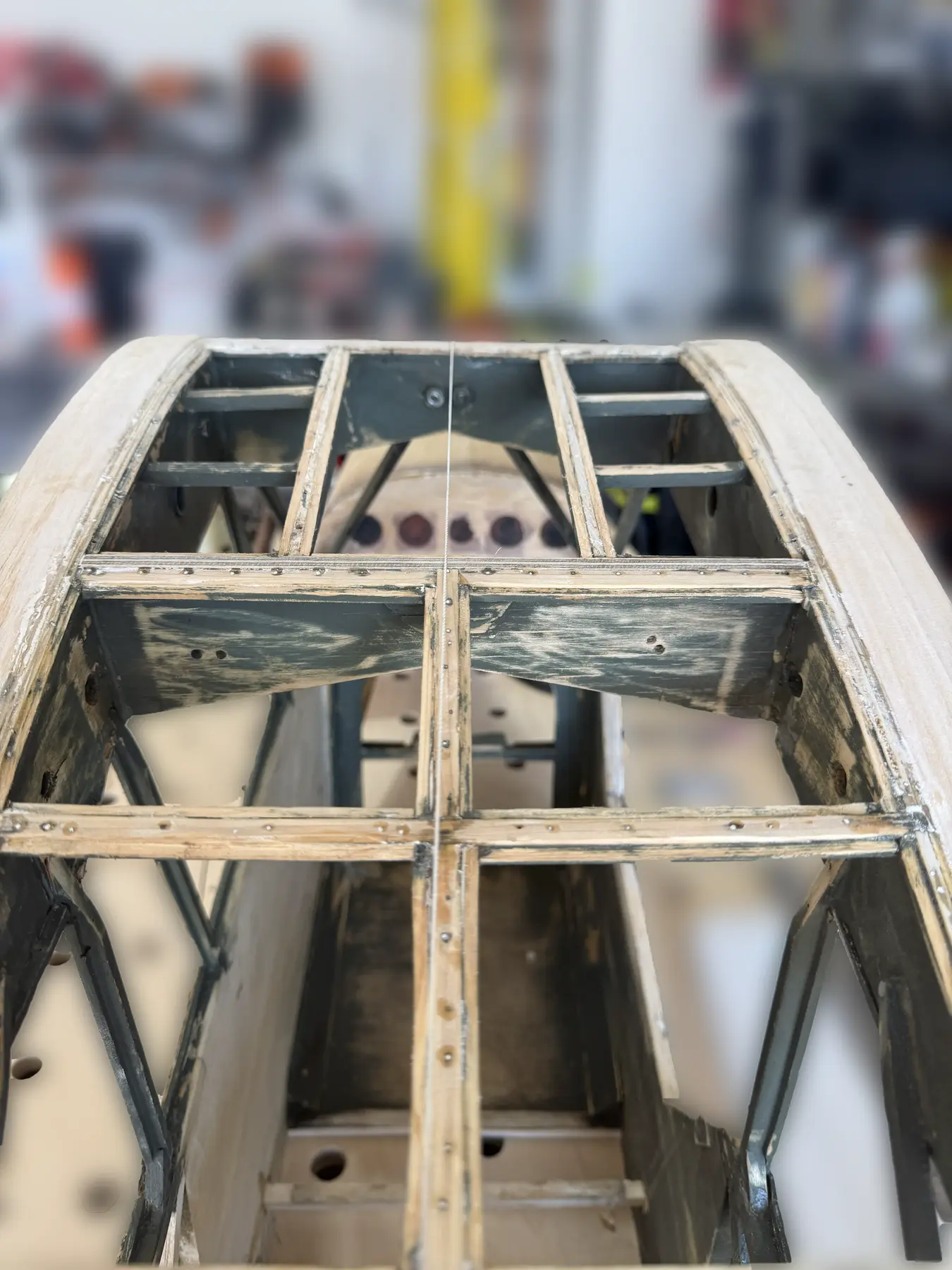
Tail-to-firewall string-line verificationA taut kite-string reference running from the tail forward around the firewall provided a continuous visual reference for checking fuselage straightness and alignment after structural repair.
Independent alignment reference
The laser review supplements the earlier physical string-line check. It is a separate reference used while the fuselage remains exposed, not a replacement for the tail-to-firewall kite string.
With the wings temporarily returned to the airframe, a laser reference was used to compare the repaired fuselage and cabin structure from additional viewing positions. The photographs document the visible reference and the structure being evaluated.
This review supports the restoration record by making unwanted bow or offset easier to see before later work limits access. It records an alignment check; it does not by itself certify the airframe or establish flight readiness.
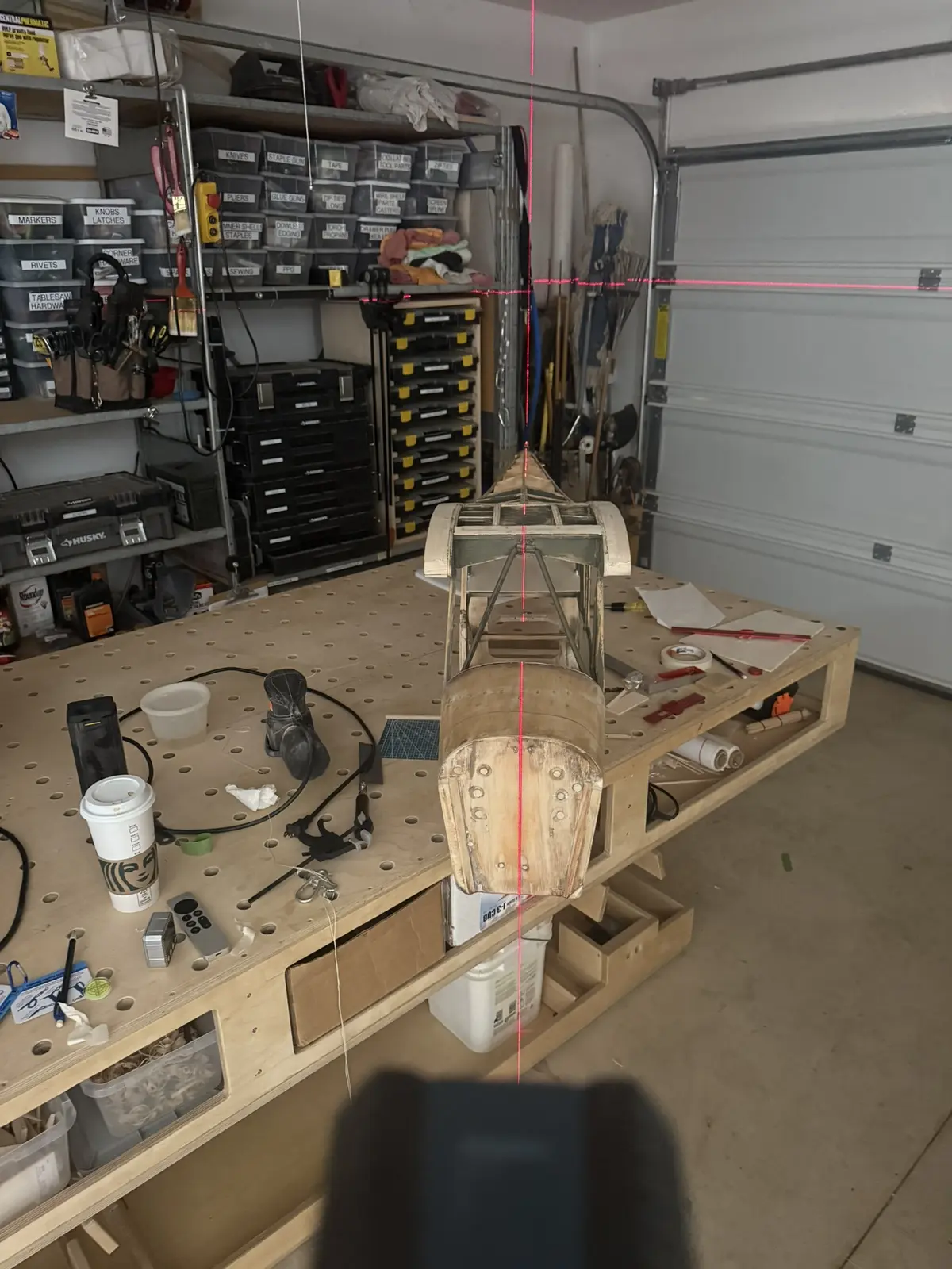
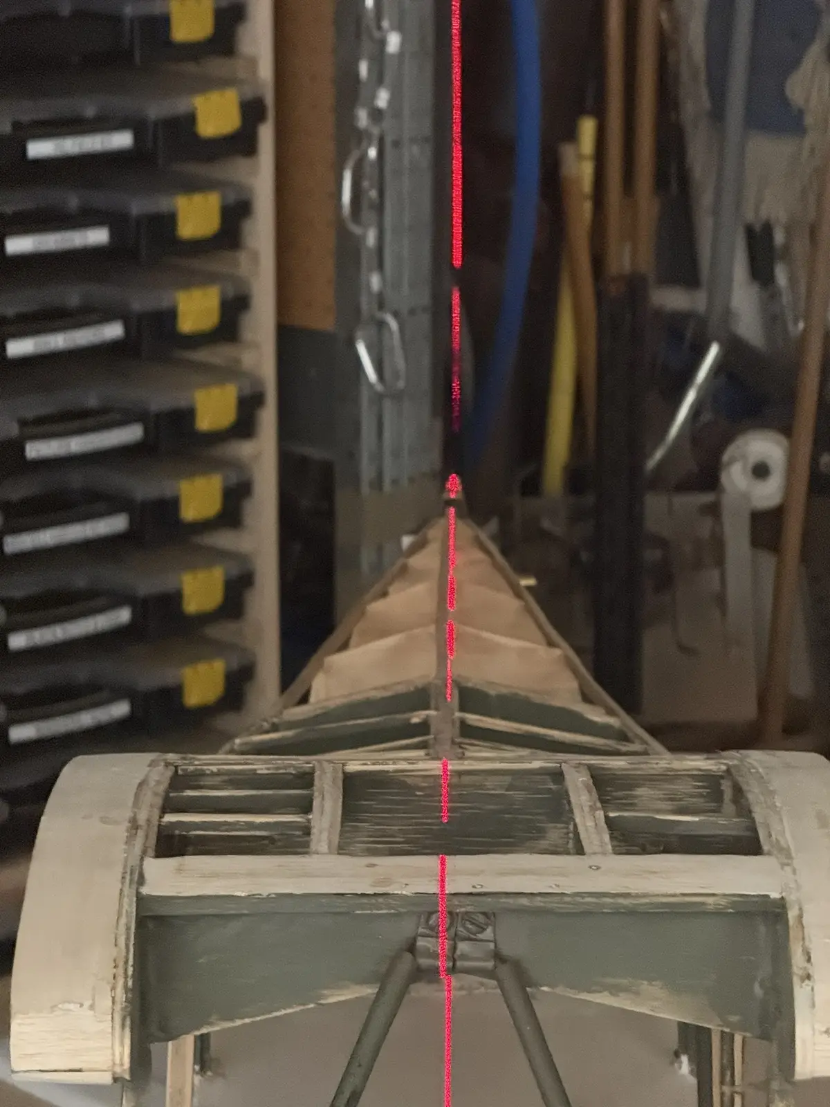
Rear-fuselage access refinement
Three access hatches remain service features rather than primary structure. Their hinge arrangement is being refined for cleaner movement, proportion and future maintenance access.
The existing hatches used relatively large pin hinges. The restoration record preserves that received arrangement while the replacement direction is evaluated around smaller hinges with approximately 10 mm square leaves and shorter legs.
The two lower hatches use two hinges each. The longer hatch, approximately 198 mm in length, calls for four evenly spaced hinges so its light access panel is supported without turning the surrounding area into unnecessary structure.
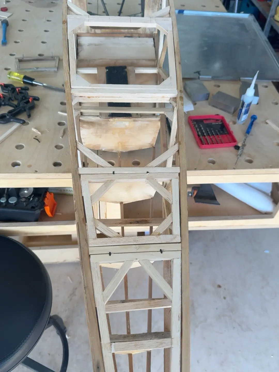
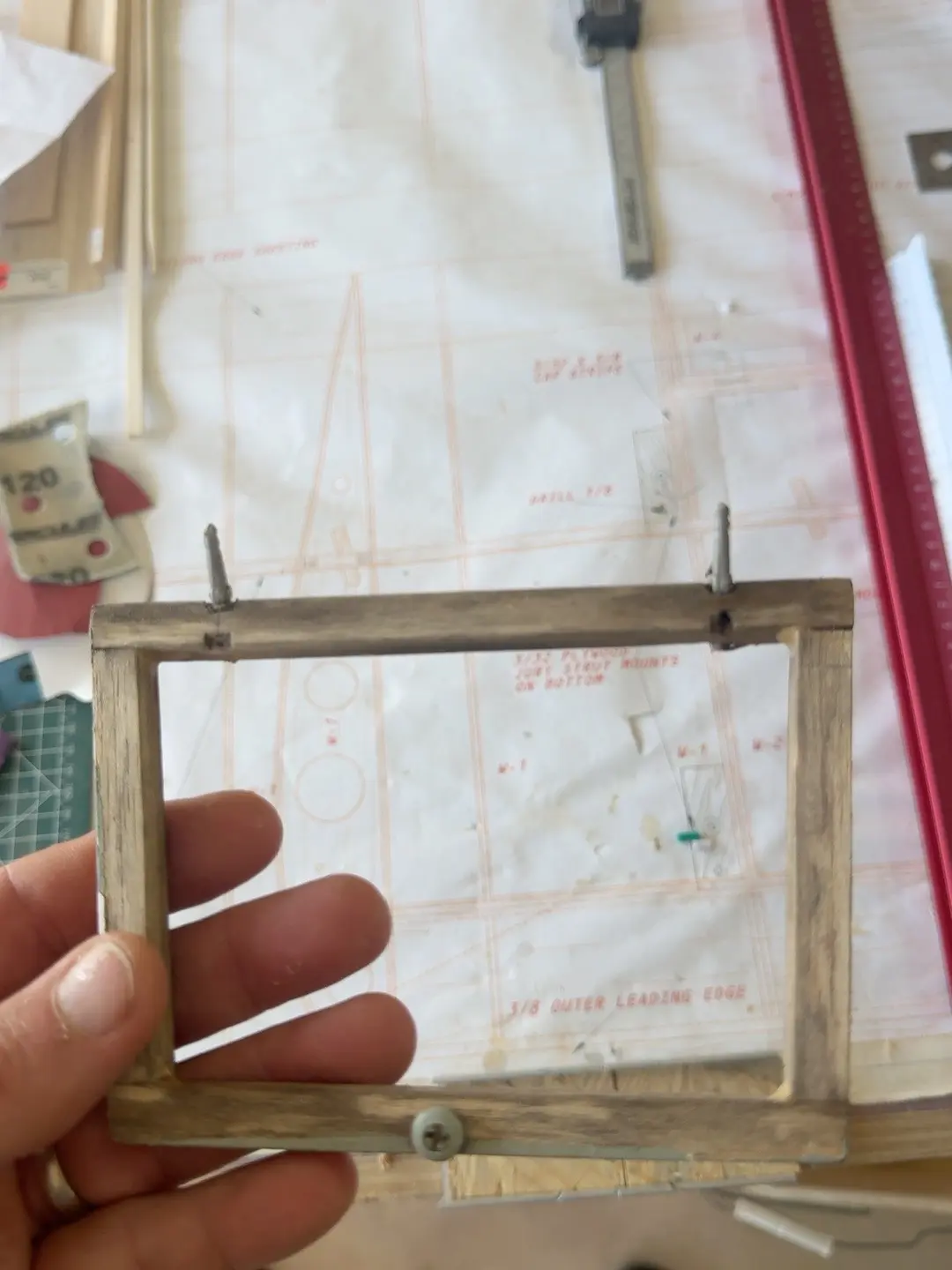
Evidence stateThe original arrangement and replacement direction are documented. Final installation and completed operation remain open until later photographs and checks prove them.
Tailpost and Support Structure
The tailpost carries the rudder hinge line and locks the rear fuselage taper. The stabilizer platform establishes horizontal-tail incidence, and the fin support establishes vertical alignment. These parts are constructed and checked as one system.
New Horizontal Tail
The horizontal stabilizer and both elevators are built new from the Balsa USA geometry. The work begins on a flat surface with a protected plan, accurately placed leading and trailing edges, straight spars, square ribs, and controlled adhesive use.
The two elevator halves must match in outline, hinge position, stiffness, travel, and control-horn geometry. The completed assembly is checked for twist before shaping, after shaping, after covering, and again at final installation.
Elevator Structure
Both elevators follow the same plan shape, hinge spacing, bevel, gap, and maximum travel.
Each elevator receives a renewed linkage with secure hardware, visible retention, and no binding through full travel.
Hinge blocks, control-horn reinforcement, joinery, and concealed structure are photographed before covering.
New Vertical Tail
The fin and rudder are built new to the Balsa USA outline and structural arrangement. The fin must mount vertically on the fuselage centerline, and the rudder hinge line must remain straight from top to bottom.
The rudder structure is reinforced where required for hinges, control horns, pull-pull attachment, and tailwheel interaction. Reinforcement remains proportional and deliberate rather than becoming an unnecessarily heavy solid tail.
Controls and Hinge Geometry
Every hinge is aligned before permanent installation. A hinge line that looks acceptable at neutral may still bind at full deflection. The elevators and rudder are trial-fitted repeatedly while gaps, bevels, clearances, control-horn positions, linkage paths, and maximum travel are established.
Pull-Pull Rudder System
The rudder pull-pull system is laid out so the servo arm, rudder horn, cable exits, and hinge line work together. Cable paths remain clear of structure and equipment, and the two sides maintain useful tension without forcing the rudder against its hinges.
Turnbuckles, crimps, clevises, threaded ends, or other terminations must be secured against loosening and documented. The final installation is inspected at neutral and at both full-deflection positions.
Tailwheel Integration
The existing tailwheel hardware is treated as a reusable component only after inspection. It is integrated into newly trusted structure rather than bolted back into damaged wood. Steering geometry, spring or linkage arrangement, rudder relationship, travel, centering, and ground clearance are checked together.
The mounting hardpoint distributes landing and side loads into the tailpost and adjoining fuselage members.
The tailwheel follows rudder command without binding, excessive leverage, or forcing the rudder linkage.
Axle, wheel, springs, tiller, fasteners, and attachment remain accessible for inspection and replacement.
Installation Alignment
The stabilizer is centered by measured distances to fixed fuselage references, not by eye. Incidence is checked against the documented datum and wing relationship. The fin is centered and made vertical to the stabilizer, and the rudder hinge line is checked against the tailpost.
Alignment is recorded before final attachment, after final attachment, and after covering tension has been introduced.
Concealed Work Record
Every splice, gusset, tailpost joint, stabilizer support, fin support, hinge block, horn reinforcement, tailwheel hardpoint, cable guide, linkage exit, and fastener backing point is photographed before covering or interior closure.
Phase 1 Completion Standard
The fuselage centerline continues through a straight tailpost; the stabilizer is centered and at the documented incidence; the fin is vertical and square.
All rear-fuselage members, platforms, hinge blocks, control-horn reinforcements, and tailwheel hardpoints transfer loads into sound surrounding structure.
Elevators, rudder, hinges, pull-pull cables, linkages, horns, and tailwheel move freely, return consistently, and remain inspectable.
All concealed work, measurements, materials, and inspection results are recorded before covering.
Edges, clearances, attachments, and service points are ready for later Koverall work without reopening completed structure.
No unresolved alignment, structural, control, or tailwheel issue remains before work advances to the wings and ailerons.
Continue the Story
With the rear fuselage straight and the complete new empennage installed, the restoration moves to the left and right wings as separate records. Spars, ribs, edges, servo installations, aileron hinges, strut hardpoints, root connections, wiring passages, and pitot integration will be inspected and corrected where needed.
Return to the Journey