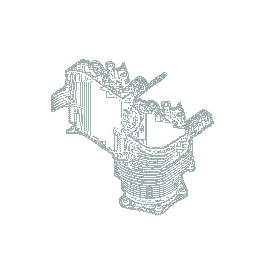
Digital geometry
An STL, STEP, SCAD or CAD file proves geometry exists. It does not prove physical manufacture.
Digital fabrication is useful because it can turn a difficult shape into something testable quickly. But a file on a screen is not a finished part, and a successful print is not proof that a part belongs on an airplane. This room follows the entire evidence trail—from idea and provenance through prototype, fit, installation and actual use.
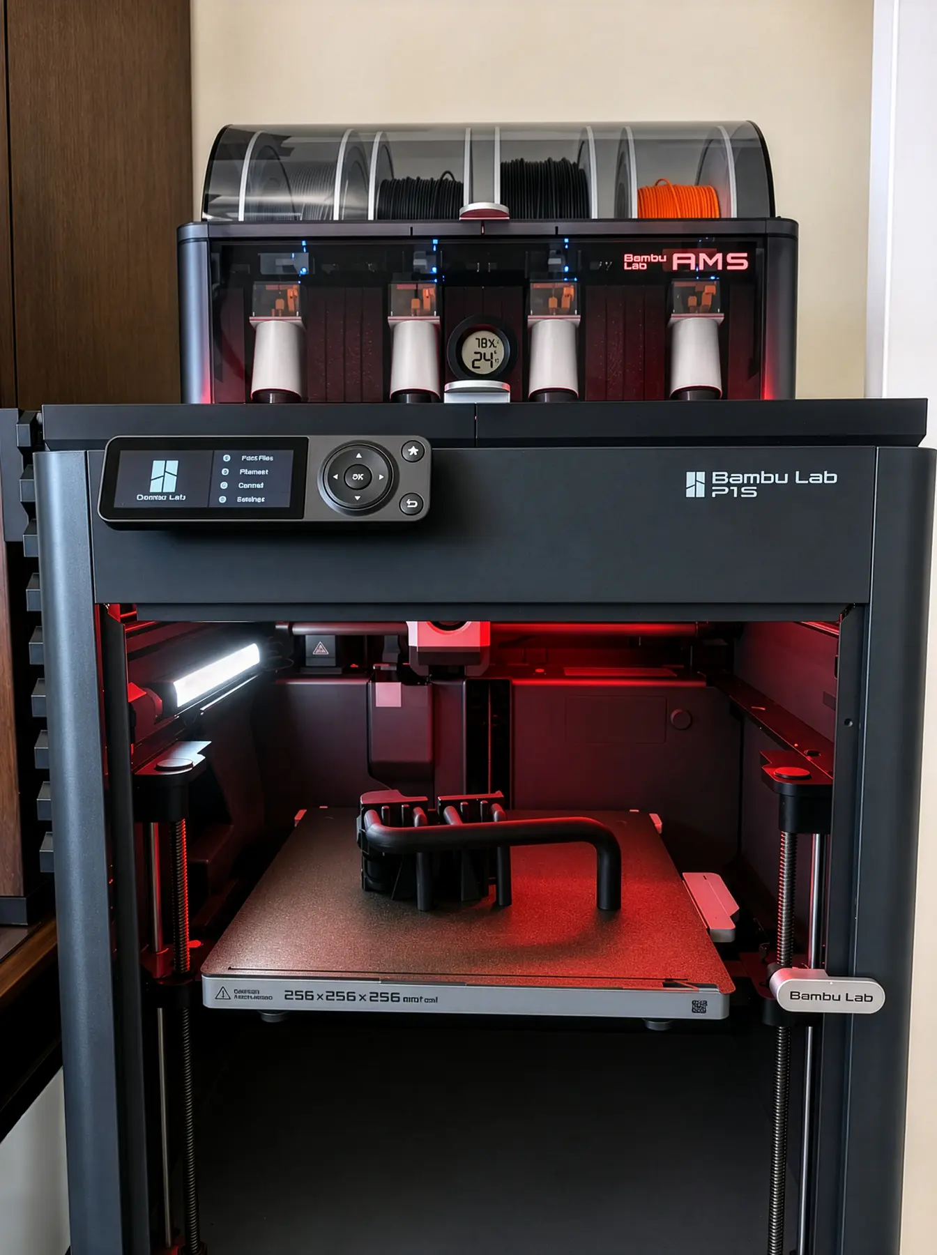
This view documents the 3D-printing workspace and process: the enclosed printer, AMS material system, active build area and aircraft-related work in progress. The printed-object photographs later in the page document the physical output separately.
The stages stay separate because each answers a different question. A beautiful STL can still be unprintable. A clean print can still fit poorly. A part that fits can still be unsuitable for the heat, vibration or load where someone wants to use it.
An STL, STEP, SCAD or CAD file proves geometry exists. It does not prove physical manufacture.
A 3MF can preserve orientation, supports, material and plate preparation. It still does not prove the print was completed.
A photograph or test article proves a physical object existed. It does not automatically prove the final revision or material was produced.
Installed, load-tested and flown or used are separate states. They are claimed only after evidence reaches those stages.
A 3D printer can change the way a model-aircraft project is approached. A missing bracket, unusual mount, scale detail or installation problem no longer has to end with a search for a commercial part that happens to be close enough.
Sometimes the right part can be designed from scratch. Just as often, a useful starting point already exists online. Digital model libraries contain parts, tools, scale details and mechanical ideas that can be downloaded, evaluated and adapted.
The important step is not simply finding a file and pressing Print. It still has to be compared with the real requirement: scale, dimensions, clearances, material, orientation, strength and the consequences if the part fails.
A 3D printer expands the choices available to a builder. The printer is not the story. The new options it gives the builder are the story.
Create a new part when nothing suitable already exists.
Begin with useful geometry and alter dimensions, mounting or features for the real project.
Resize an existing model or scale component to suit the aircraft.
The best solution does not always need to begin from zero. Good fabrication includes knowing when to design, when to modify, and when existing digital work can shorten the path to the part actually needed.
Scale engines, instrument bezels, light housings, cable clips, pitot mounts, servo brackets and countless other useful parts may already exist in online model libraries. When they do not, the printer makes it possible to design a solution from scratch.
The possibilities are limited less by the printer than by the builder’s imagination, willingness to search and ability to adapt an idea to the project.
A downloaded part is a starting point for evaluation—not automatic proof that it is suitable for aircraft use.
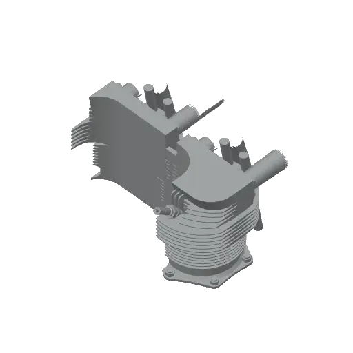
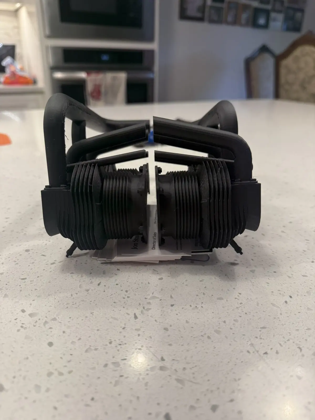
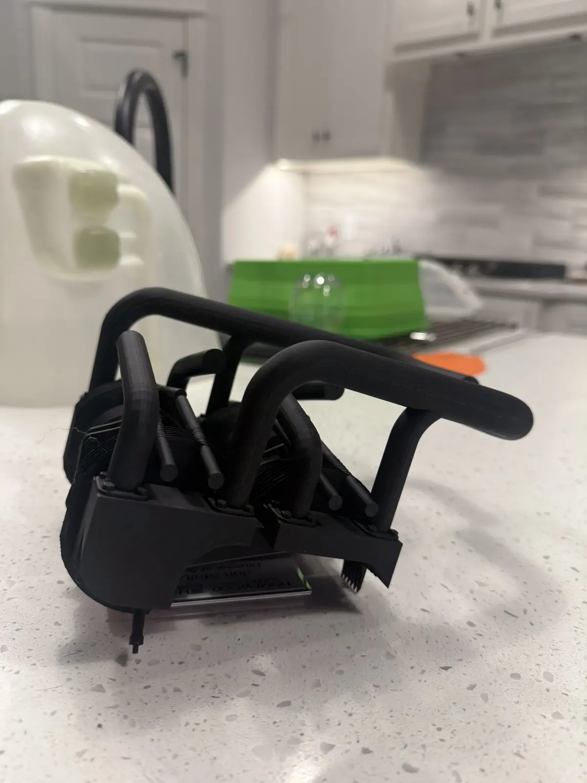
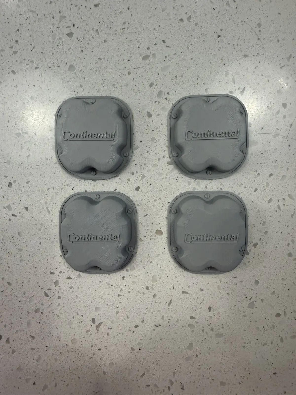
Rather than beginning with a blank CAD screen, an existing digital engine model provided the starting geometry. For the one-third-scale L-4, the one-quarter-scale model was enlarged to approximately 133.3%, separated and modified where necessary, prepared for printing and produced as a physical PLA prototype.
The prototype could then be compared with the actual airplane and cowl. Geometry that looked appropriate on screen could be judged in the real installation. The cosmetic engine remains mechanically independent from the actual electric propulsion system.
Lynxman's purchased third-party Piper Cub dummy-engine model, with source and authorship retained.
Enlarged from 1/4 scale to 1/3 scale at approximately 133.3% and prepared for the P1S.
The PLA prototype made cowl fit, scale position, clearance and visual effect physically judgeable.
Final PETG-HF production and installed final state remain open until later evidence proves them.
The process was not download → print → finished. It was:
Purchase does not automatically grant redistribution rights. Any future download offering depends on the actual license terms.
The evidence follows one chain: prepared → printed → assembled → fit-checked → revised. Final PETG-HF production and installation remain open.
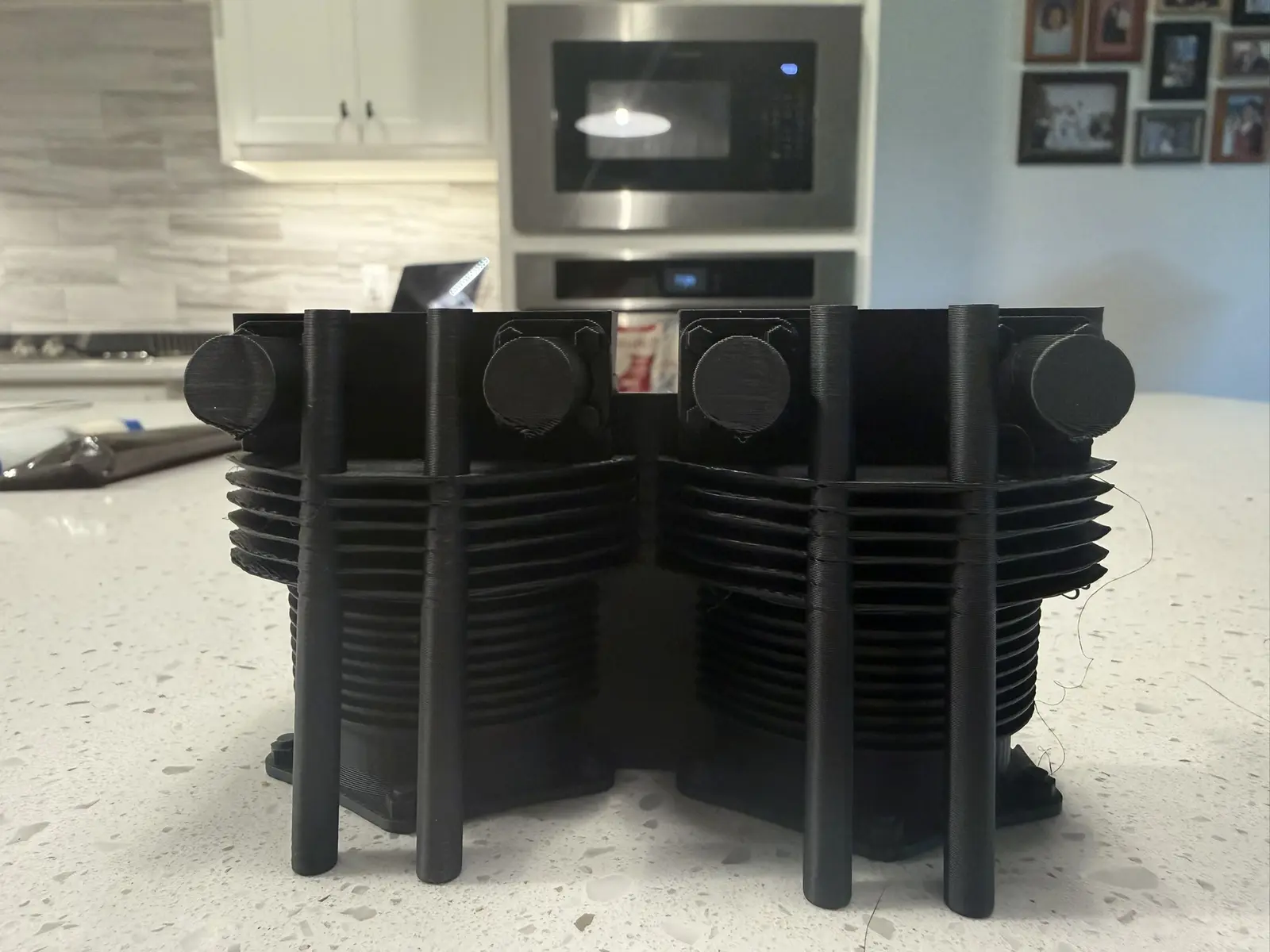
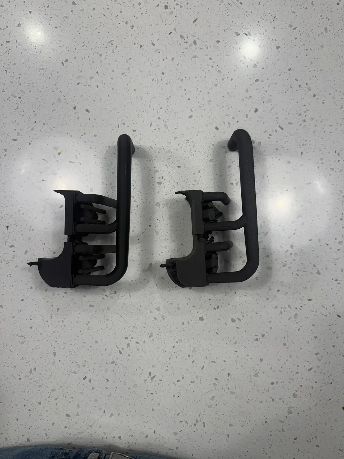
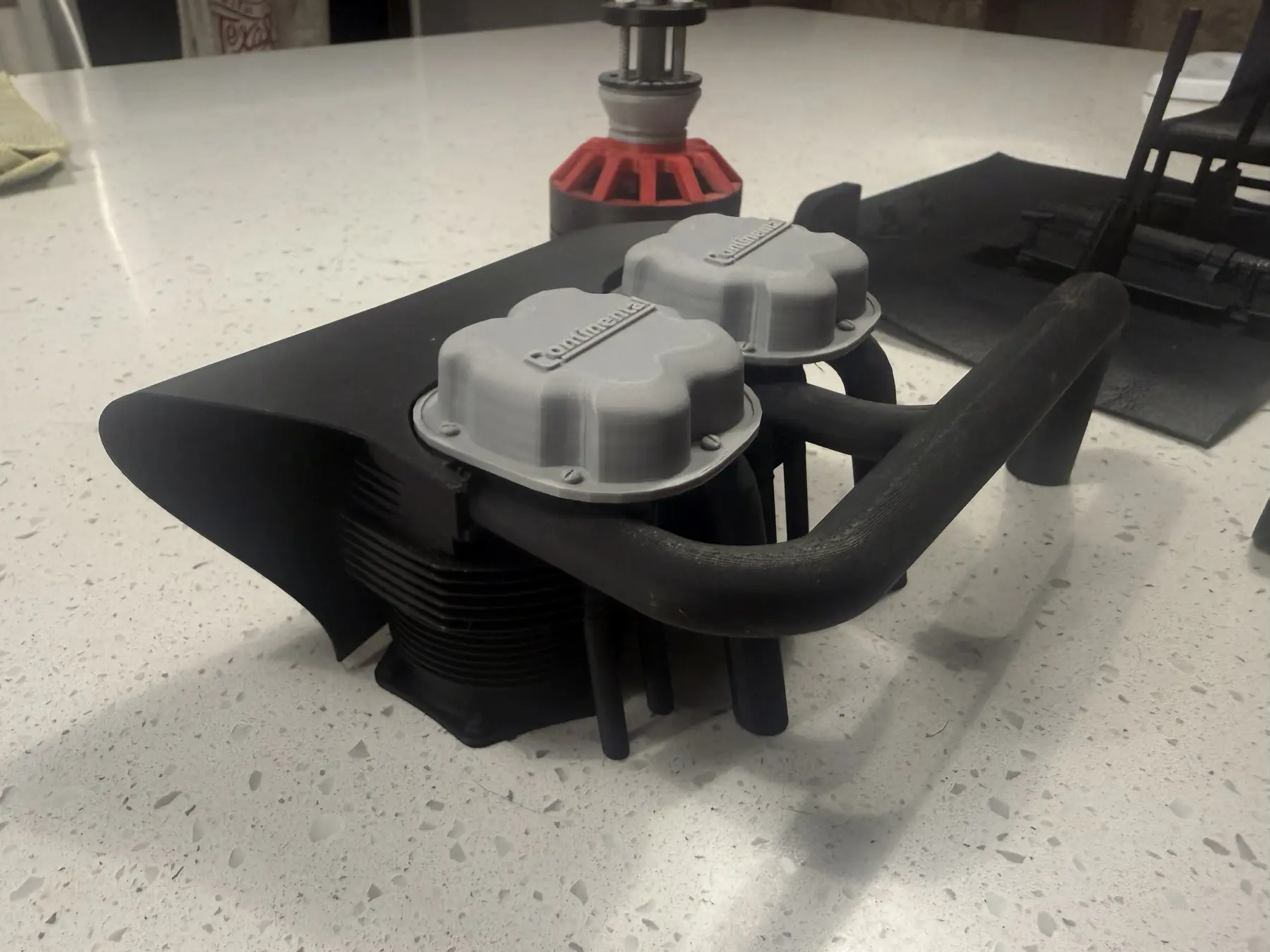
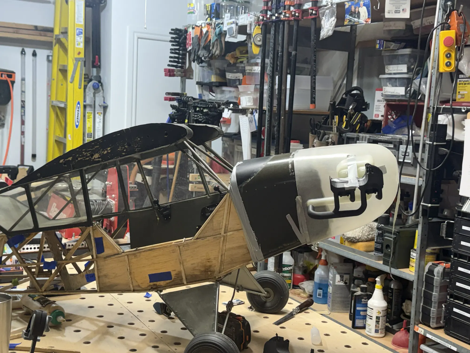
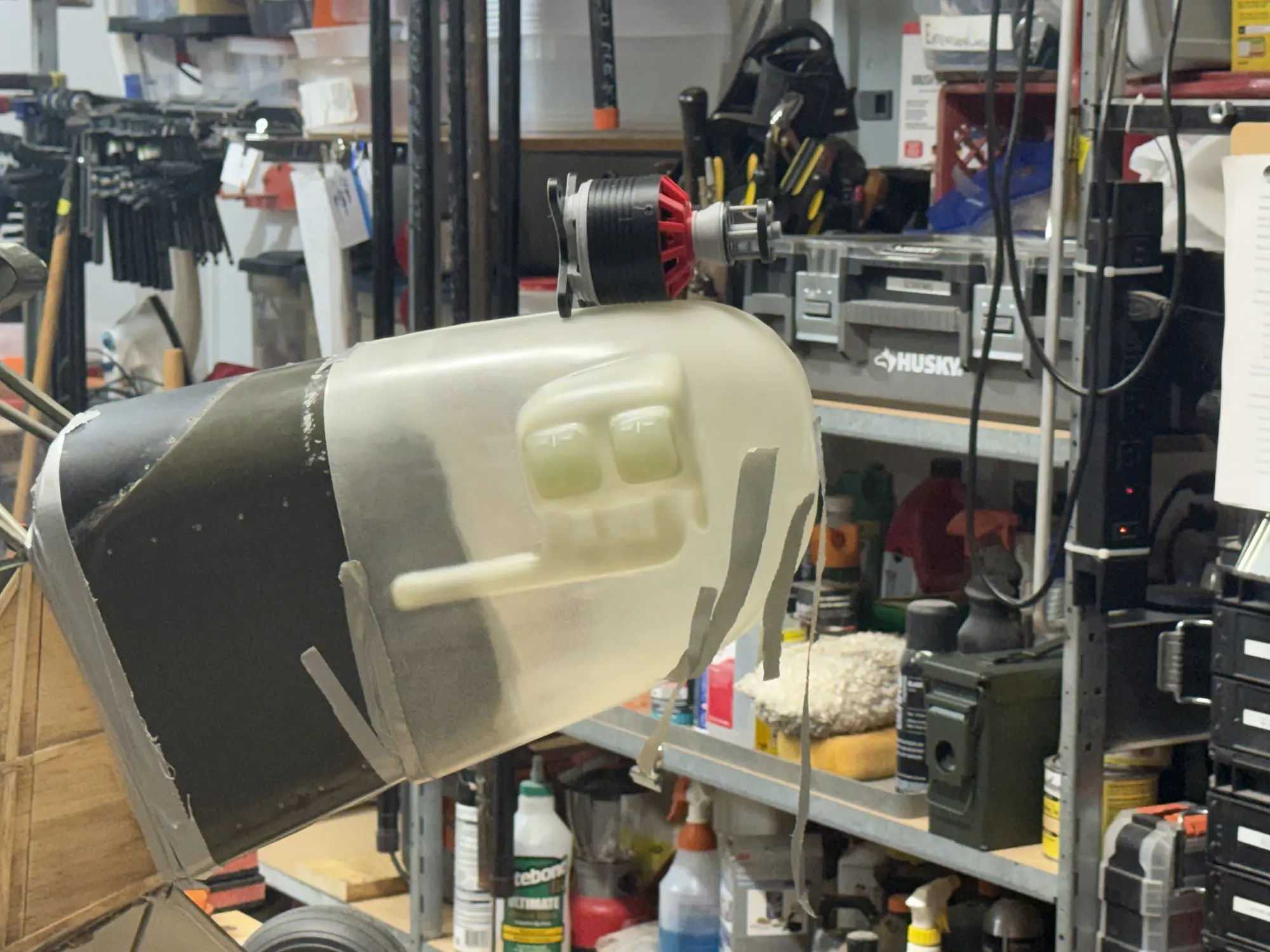
Jon's archive documents the physical sequence without turning prototype evidence into a finished-installation claim.
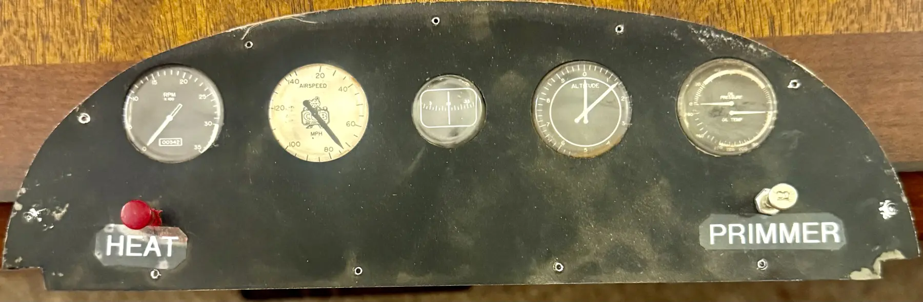
The work began with the actual airplane: opening geometry, width, lower notch, top arc, side shoulders and instrument positions. Printable geometry then turned digital assumptions into a physical object that could be checked against the L-4.
1 · Print to learn.
The prototype converted full-size measurements into something that could be handled and checked.
2 · Compare with the aircraft.
The center and upper shape validated much of the model while outer curves revealed where correction was needed.
3 · Revise without overclaiming.
A prototype that exposes an error has converted uncertainty into a measurable next revision.
4 · Preserve provenance.
Panel structure, reference imagery, reconstructed dial art and scale output retain separate origins.
A lightweight aircraft part is not created simply by reducing infill everywhere. Strength can often be placed more efficiently through geometry, orientation, local reinforcement, walls, ribs and thoughtful material choice.
Printed parts benefit from familiar model-building thinking: put material where it contributes and remove it where it does not. Small test prints and fit prototypes can expose problems before time and material are committed to a final version.
Choose print orientation before adding unnecessary material.
Use walls where shape, screw support and edge strength matter.
Use modest infill where the shell carries most of the job.
Reinforce mounting points locally.
Use ribs and flanges rather than making everything solid.
Divide parts when separate printing improves orientation.
Prototype first when fit is uncertain.
Judge failure consequence before choosing print use.
Useful when the goal is to learn quickly from a physical object. Its lower heat tolerance still matters.
A logical next step when a proven prototype becomes a working component.
Worth evaluating when heat and UV justify it—not an adopted Hangar standard.
A possibility where compliance is useful, not a claim of established use.
The numbers only make sense in the context of the job, material, geometry and evidence state. Three real records show why one recipe cannot be copied across every project.
The first plate tests clip sizes on the actual braided harnesses before production quantities are chosen.
Design and preparation exist; physical print, installation and load validation remained open in the recovered record.
This lighter shop profile shows that different jobs lead to different settings. It is not an aircraft-part recipe.
The source files preserve a compact development story: reference geometry became test sizes, actual braided harnesses determine which sizes are useful, and the geometry is narrowed and revised before production quantities are chosen.
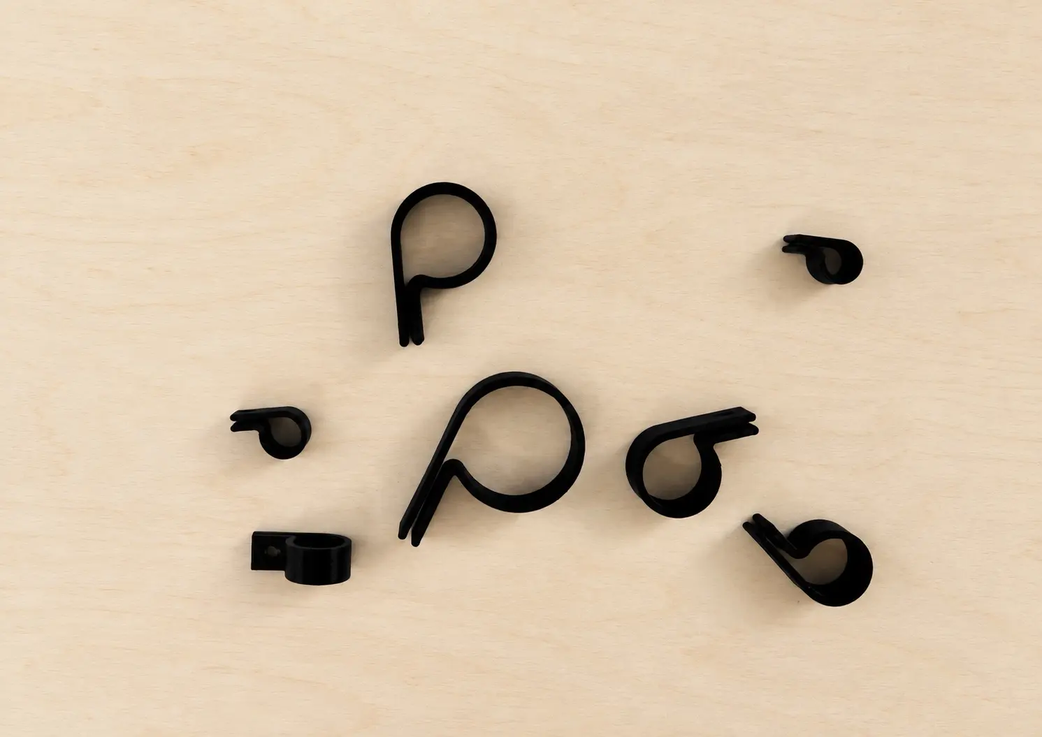
Once a printer becomes part of the normal build flow, small problems begin to look different. A wire that needs support suggests a clip. A light needs a housing. A sensor may need a mount. A repeated drilling operation may justify a jig.
Not every solution should be printed—but the printer gives the builder another option to consider.
The proposed library turns measurements from owned equipment into lightweight, 1:1 PLA stand-ins. Those stand-ins can be placed in an unfinished aircraft without repeatedly handling expensive electronics while a tray, service opening or wire route is still changing.
The useful model is not only the component body. It is the complete installation envelope.
Compare candidate positions, trays and access openings at full scale before committing the aircraft structure.
Add simple stand-in wires or tubes to represent connectors, antenna exits, heavy leads, bend radius and service loops.
Check that batteries and equipment can be inspected and removed without disturbing unrelated systems.
Keep verified mock-ups and clearance gauges for the L-4, J-3 and future aircraft rather than solving the same packaging problem twice.
Evidence state: the component measurements and library concept are established. No completed physical mock-up library is claimed until the first printed stand-ins are photographed and checked.
See the L-4 bench measurements and installation-envelope requirements →
Each project stops wherever its evidence stops: idea → sourced or designed → modified → sliced → printed → fit-checked → installed → tested → used.
| Project | What is proven | What remains open |
|---|---|---|
| L-4 instrument panel | Measurements, printable geometry, PLA prototype and physical fit evidence. | Corrected final geometry, final print and installed state. |
| L-4 Continental | Attributed starting model, 133.3% adaptation, PLA prototype and cowl fit. | Final PETG-HF production and final installation. |
| Aircraft P-clips | Documented fit-test settings, size assortment and revision path. | Confirmed production sizes and installed/use state. |
| Carbon Cub hanger | Jon-defined need, 215.9 mm width, AI-assisted STL and proposed PETG plan. | Physical print, mounting, load test and use. |
| Carbon Cub tray / VGs / cowl | Digital project files and selected provenance records. | Print, fit, installation and operational states vary. |
| Propeller balancer | Printed-component geometry supporting a mechanical concept. | Complete assembly, calibration and proven service. |
Printed cones, spacers, lift blocks and magnet mounts can support a larger mechanical balancing system. But the result depends on rod, magnets, tower geometry, clearance, alignment and friction.
Current reconciled geometry uses an 8 mm × 200 mm round steel rod.
Rectangular magnets are horizontal with the rod approximately perpendicular to their long faces.
Greater tower height supports larger propellers and giant-scale work.
A balanced propeller should remain neutral through several angular positions rather than falling to one heavy point.
No finished or working state is claimed without assembly and test evidence.
A decorative cockpit detail, cable guide and flight-critical control component do not carry the same consequences if they fail. As consequence increases, so should scrutiny of material, geometry, fasteners, orientation, testing and whether additive manufacturing is appropriate at all.
| Class | Typical use | Validation expectation |
|---|---|---|
| A · Cosmetic | Dummy engine, bezels, cockpit detail. | Quality, appearance, fit, heat and environment. |
| B · Support equipment | Prop balancer, ceiling hanger, shop fixtures. | Real load, mounting, environment and safe-use test. |
| C · Functional, non-catastrophic | Wire guides, sensor mounts, antenna supports. | Material, retention, vibration, temperature and serviceability. |
| D · Flight-critical | Firewall, engine mount, gear mount, strut fitting, control horn, hinge. | Do not substitute a hobby print where failure can directly mean loss of the aircraft. |
Searching model libraries makes provenance more important, not less. A downloaded design should not become mislabeled as an original, and an AI-assisted design should not be described as hand-modeled CAD work.
Record requirements, revisions and evidence state without implying unproven testing.
Use when Jon supplied requirements and intent while AI materially assisted geometry.
Preserve the creator and source, then describe exactly what changed.
Credit the designer and license. Possession or purchase does not imply redistribution rights.
See the panel, dummy engine and restoration context.
Follow propulsion mockups and printable opportunities.
Follow digital-support projects and evidence states.
Move from printed fixtures into loads and shop workflow.
See where printed mounts may support electrical architecture.
Find controlled drawings, references and downloads.
See the strongest fabrication milestones.