RF-band diversity
Two frequency bands can improve link resilience when the transmitter and receiver system are designed to use them together. FrSky Tandem's simultaneous 2.4 GHz + 900 MHz capability is one example.

This is where the invisible parts of an aircraft become understandable: radio links, receiver architecture, redundant power, servos, wiring, telemetry, programming and failure testing are treated as one system rather than a pile of boxes connected by hope.
The Electronics Bench follows every signal and power path through the installed aircraft. The photographs keep that work tied to the control linkage and the cockpit structure it must ultimately serve.

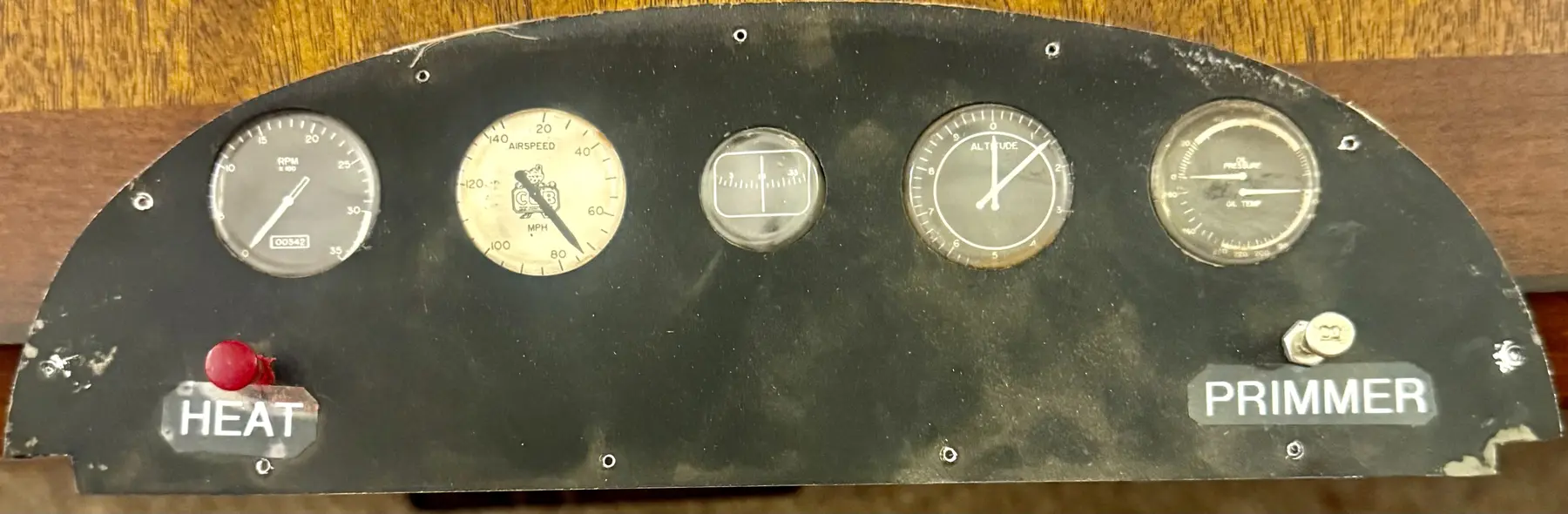
Electronics design starts with consequences rather than product names. A propulsion failure should not automatically remove control. An accessory fault should not collapse the receiver bus. A single connector, battery, receiver path or programming change should not quietly become the point where the whole aircraft depends on one thing working perfectly.
Two frequency bands can improve link resilience when the transmitter and receiver system are designed to use them together. FrSky Tandem's simultaneous 2.4 GHz + 900 MHz capability is one example.
More than one receiver path can reduce dependence on a single receiver or local antenna environment. Exact implementation belongs to the aircraft being built.
Independent receiver-power paths protect flight controls from one battery, lead, connector or power-path failure.
Independent control surfaces or channels can reduce single-point failures, but this is not automatically created by having two receivers.
A system may have one kind of redundancy without the others. The Electronics Bench keeps those layers explicit.
The giant-scale projects drove a requirement for RF diversity, telemetry, diagnostics, expandable receiver architecture and a programming environment that could support complex aircraft without turning the radio into a black box.
Earlier RadioMaster / EdgeTX / ELRS work remains valuable design history because it sharpened the redundancy questions. The present giant-scale ecosystem is FrSky Tandem X20R / ETHOS, while each aircraft still controls its own exact receiver, power, antenna, stabilization and failsafe implementation.
Owning the transmitter does not prove a specific receiver pair, antenna arrangement or stabilization system is installed in every aircraft.
Superseded receiver and RF studies are preserved when they explain how the current design questions were reached.
Learn screens, widgets, model creation and model selection.
Assign switches, verify the channel monitor and confirm direction before connecting a live propulsion system.
Register, bind, discover sensors and understand what data is actually present.
Add flight modes, logical switches, voice alerts and failsafe behavior only after the basic control path is understood.
Prop removed. Control movement verified. Failsafe checked. Then repeat after every material programming change.
Receivers, power hub/distribution, control servos and required aircraft-allocated sensors.
Motor, ESC, propulsion batteries and propulsion-specific instrumentation.
Lighting, cameras, recording systems and other non-critical loads unless an aircraft-specific safety decision says otherwise.
A telemetry connection between domains is not allowed to become a hidden power dependency.
The RB25S is part of the current giant-scale architecture work, but this room does not assign one physical installation to every aircraft. Aircraft-specific pages remain authoritative for whether a hub is allocated, mounted, wired, tested and released.
Two receivers mounted together with antennas bundled in the same orientation can share the same shielding, polarization and impact vulnerabilities. Final receiver pair and geometry remain aircraft-specific decisions.
Separate useful antenna locations, avoid obvious shielding and high-current conductors, use useful polarization diversity, test in the finished aircraft and record final geometry.
Mechanical first. Electronics second. Load, geometry, speed, durability and linkage quality come before programming convenience.
Separate elevator, aileron or flap channels can improve adjustment, diagnosis and fault isolation when the aircraft design calls for them.
A load study may define required capability without locking a manufacturer or model.
Purpose-made wiring reduces adapter chains, unsupported connectors and mystery junctions. The goal is a harness that can be inspected, understood and repaired.
A connector used every flying day deserves the same design attention as a component buried inside the fuselage: visible engagement, positive orientation, left/right identification, protected service loop, recorded pinout and continuity check after assembly.
Telemetry earns its place when it answers an operational question. It is advisory and diagnostic; it is not primary flight authority.
Receiver-bus voltage, power-path state and RF/link information can reveal developing problems.
Voltage, current and capacity-used data can help explain propulsion demand and battery behavior when the final aircraft has the required interfaces.
Motor, ESC, battery-bay or other temperatures are useful only after actual sensor location and calibration are known.
GPS and pitot airspeed can support awareness, testing and post-flight analysis when allocated and calibrated.
The broader FrSky record proves ownership of GPS ADV, PAS70 ADV and PT100-class sensor capability. That does not automatically mean those devices are installed in the L-4, quarter-scale Cub or another aircraft.
If everything talks, nothing sounds urgent. Highest priority belongs to control-link health, receiver-bus voltage and receiver-power/failover conditions; routine data can remain on demand or be spaced deliberately.
Stabilization remains an aircraft-specific choice. Any implementation must be checked for sensor orientation, correction direction, gain, mode behavior, switch logic and failsafe interaction. It is never a substitute for correct CG, straight structure, free hinges, proper linkage geometry, sound control surfaces, basic trim or pilot control.
Power inputs, hub/distribution, receivers, servos, sensors and switches checked separately.
Complete control architecture under simultaneous servo load while deliberate failures are introduced.
Range, orientation, interference, motor-running environment, wing assembly and service access tested in the real airframe.
Unplug what the system claims it can lose: Receiver Battery A, Receiver Battery B, primary receiver path, redundant receiver path, selected sensor, confirmed non-critical accessory branch and propulsion interaction. Ask: did control continue, did the correct warning appear, and did the fault propagate?
Final range work is repeated with the aircraft in multiple orientations and, where safe, with propulsion operating. Investigate link-quality degradation, resets, jitter, telemetry dropout, sensor instability, voltage dips, orientation sensitivity and abnormal temperature rise.
Firmware, receiver settings, wiring, endpoints, gains, battery assignments, warnings and failsafe are configuration-controlled. Material changes trigger the relevant tests again. The as-flown record belongs at the end of the evidence chain, not the beginning of the design process.
Redundant control power and telemetry in the Grasshopper restoration.
Go to the L-4 →Current FrSky architecture, purchased servos and still-open receiver implementation.
Go to the Cub →Access, mounts, wiring routes and serviceability before covering closes the structure.
Go to Workshop →Fixture, tray and prototype work around electronics integration.
Go to 3D Print Lab →Release testing, range work, telemetry review and as-flown records.
Go to Flight Line →Manuals, diagrams and controlled technical references.
Go to Plans Room →