Why map defects?
A numbered record prevents a visible crack from receiving attention while a hidden load-path problem is forgotten.
L-4 Grasshopper
Twelve visitor chapters follow the aircraft from its as-received condition through teardown, reconstruction, systems integration, finish, ground testing, flight release, and long-term preservation.
Each chapter explains what is being done, why the decision belongs in this restoration, and how it connects to the aircraft as a whole.
The restoration in view
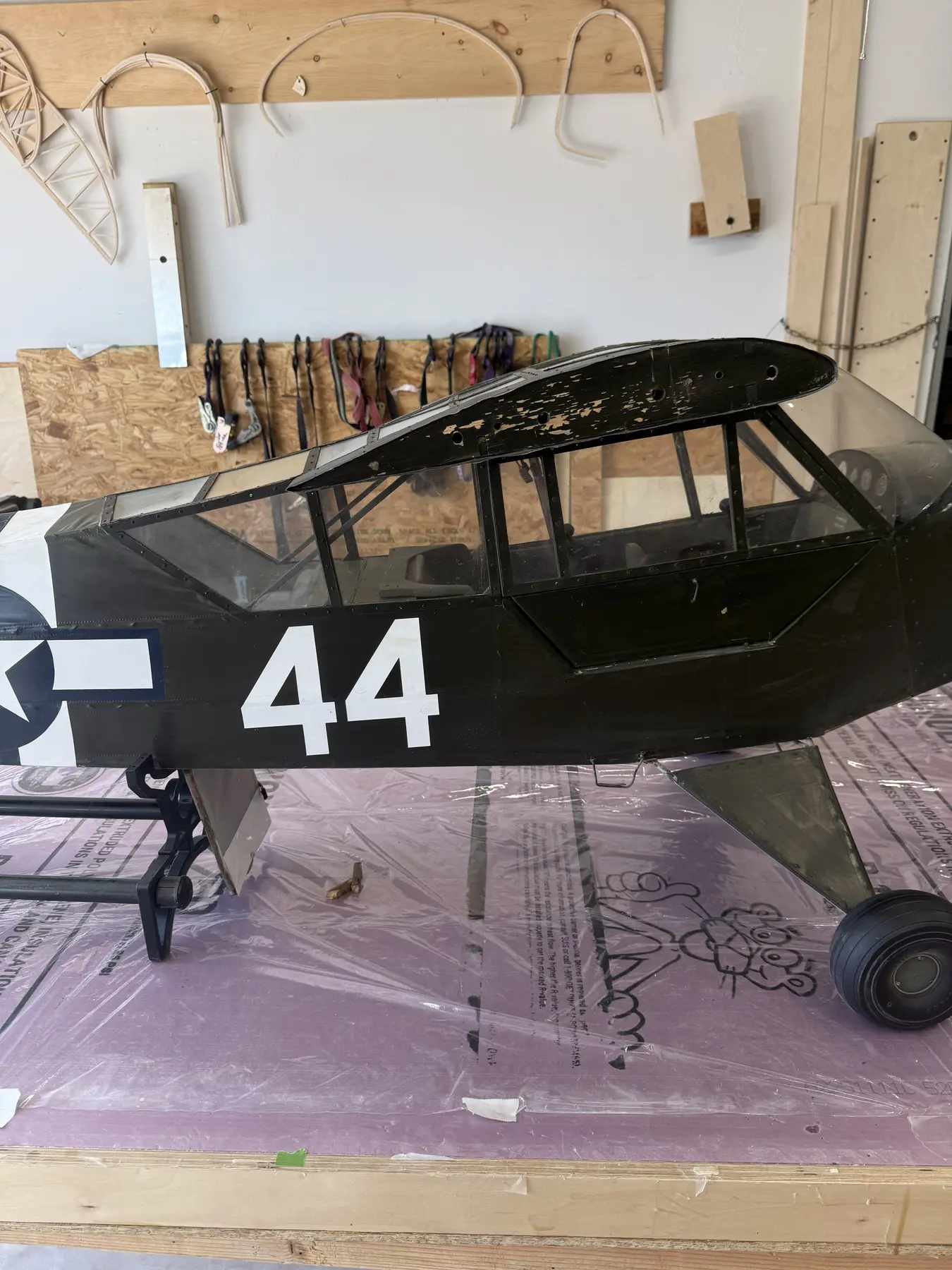
The journey begins with the acquired aircraft and follows it onto the bench, where structure, systems and earlier workmanship can be inspected honestly.
How to Read the Story
What was found? What is being preserved? What requires repair or complete reconstruction? Why was that decision made? What evidence supports it? What was added for authenticity, durability, serviceability, or safe RC operation?
The project avoids two extremes: blindly preserving weak or inaccurate construction and redesigning a developed aircraft simply because another solution is possible.
The Twelve Chapters
Chapter 01
The complete aircraft is recorded before restoration work changes it. The existing model is treated as evidence because even a weak or unusable part may preserve dimensions, geometry, hardware locations, and the original builder's intent.
Why: A restoration cannot make honest decisions after the evidence has been trimmed, discarded, or altered.
Chapter 02
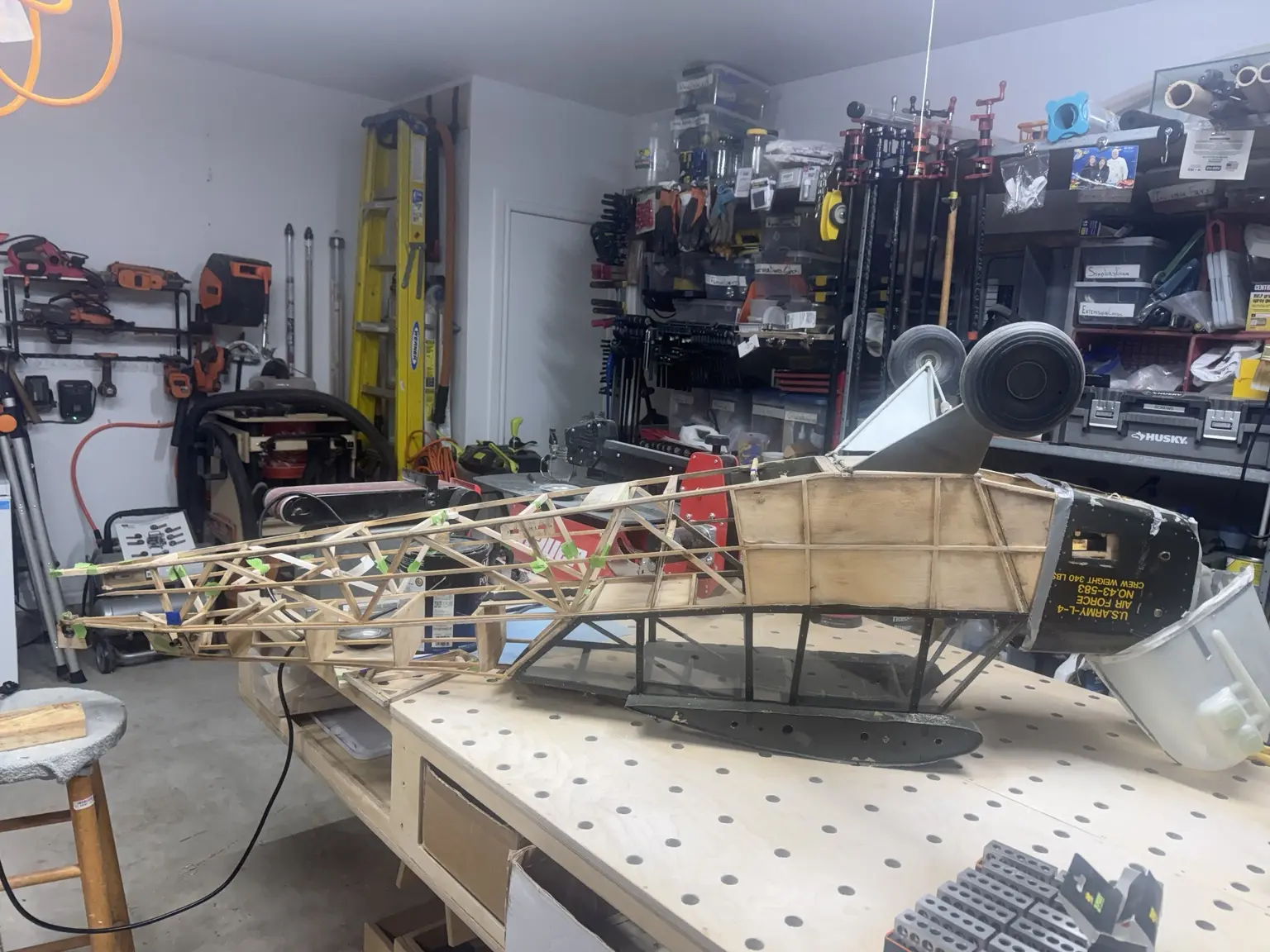
With the covering removed, cracks, failed joints, prior repairs, weakened hardpoints, missing parts, and sound original construction are mapped before repairs begin.
A numbered record prevents a visible crack from receiving attention while a hidden load-path problem is forgotten.
Old glazing, hardware, or damaged structure may contain the only surviving pattern or assembly clue.
Plans control geometry, the model records its received configuration, and history guides supported appearance.
Chapter 03
The existing greenhouse is a developed installation and remains the restoration baseline. Sound framing and operating relationships are preserved; aged clear material is replaced with 0.040-inch PETG.
It records a coherent builder-developed configuration and gives the airplane much of its L-4 identity.
Clear, durable, formable material supports repeatable panels and practical fastening without forced distortion.
A decorative closure is not sufficient on a flying giant-scale model exposed to vibration and airflow.
Chapter 04
The lower fuselage, belly hatches, landing-gear structure, firewall, cockpit supports, and battery system are rebuilt as one connected structure.
Landing, motor, battery, and equipment loads must travel into sound surrounding structure rather than ending at isolated plates or brackets.
Hatches must fit the maintenance task without cutting through the structure that makes the fuselage rigid.
The known two-6S architecture requires safe volume, support, retention, cooling, and access while exact pack size and balance position remain adjustable.
Chapter 05
The damaged tail area is not patched around. The fuselage is jigged straight, a centerline and datum are established, and the complete empennage is built new from known Balsa USA geometry.
Weak or distorted tail surfaces are valuable as reference but cannot be trusted as flight structure.
A strong new tail built onto a twisted fuselage would only make the alignment error permanent.
Hinges, horns, pull-pull cables, and linkages must transfer load freely and repeatably through the full travel range.
Chapter 06
The left and right wings receive separate records. Structure, roots, strut hardpoints, ailerons, hinges, servos, connectors, wiring, and the pitot system are inspected and tested as complete assemblies.
A condition on one wing prompts inspection of the other but does not prove that both are identical.
Transmitter adjustment cannot correct unequal hinges, flexing mounts, poor horn geometry, or a twisted surface.
Airspeed data becomes useful only after leaks, zero, tubing, location, and actual field readings are proven believable.
Chapter 07
The existing molded cockpit pieces are restored as both visible scale presentation and removable access to the modern systems beneath them.
It is part of the acquired aircraft's developed configuration and preserves the earlier builder's work.
Detail is concentrated where the greenhouse reveals it, avoiding unnecessary weight in hidden areas.
Scale appearance must not trap batteries, receivers, wiring, linkages, or inspection points.
Chapter 08
The X20R and RB25S architecture uses two independent 2S LiFe receiver batteries and separates flight-critical control from propulsion and accessories.
Two independent power paths allow either pack, lead, connector, or input to be lost while the other continues carrying the control load.
Receivers and antennas must not share one location, orientation, shielding problem, or interference environment.
Data is selected to expose developing faults, guide action, and explain postflight events—not to decorate the transmitter screen.
Chapter 09
The L-4 uses a locked 12S architecture made from two 6S propulsion packs in series. The design favors a low-Kv high-torque motor and a large efficient propeller turning at moderate RPM.
The exact motor, ESC, propeller, pack capacity, pack dimensions, connectors, cooling details, tray position, and final center-of-gravity location remain open until the completed aircraft supplies reliable measurements and test data.
The L-4 needs strong low-speed pull, grass-field takeoff authority, climb, and go-around thrust—not high-RPM sport-airplane speed.
Higher voltage allows the required power at lower current, reducing voltage drop and resistive heating when the system is correctly matched.
Routine flight should be easy, cool work, leaving additional thrust for takeoff, climb, wind, and a rejected landing.
Chapter 10
SIG Koverall closes the restored structure and becomes the foundation for a clean operational U.S. Army Normandy presentation with full invasion stripes. Fabric, tapes, paint, markings, glazing, and final assembly are treated as one controlled system.
Covering can hide unfinished work, restrict access, introduce distortion, and make later corrections unnecessarily destructive.
Fabric tension can twist a surface, while excessive coating increases wing loading and buries the scale fabric character.
Full invasion stripes establish the Normandy period, but aircraft-specific markings remain honestly classified until evidence supports them.
Chapter 11
The aircraft passes through complete-system bench testing, failover demonstrations, servo-load testing, range checks, telemetry validation, pitot testing, progressive power runs, taxi work, and repeated structural inspection before flight.
Why: The maiden flight should confirm a tested aircraft—not become the first time multiple new systems are asked to work together.
Chapter 12
Postflight inspection, telemetry review, recurring maintenance, transportation protection, battery handling, PETG care, storage supports, and configuration-change records preserve both the aircraft and the truth of the restoration.
Why: A signed As-Flown Configuration Record only remains meaningful if later structural, electrical, programming, battery, or balance changes are recorded and retested.
Continue Exploring
The L-4 restoration connects to structural work in the Workshop, radio and telemetry work at the Electronics Bench, printed scale details in the 3D Print Lab, records and drawings in the Plans Room, and testing at the Flight Line.