Photograph
Overall views, root fittings, spars, rib bays, hardpoints, servo installations, hinges, horns, and every concealed repair.
L-4 Restoration · Chapter 06
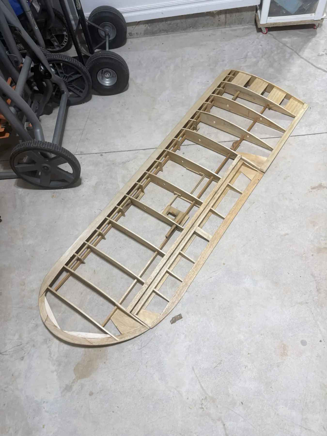
The wings were among the better-preserved major assemblies when the aircraft was acquired, but good overall condition does not remove the need for a complete structural and systems inspection.
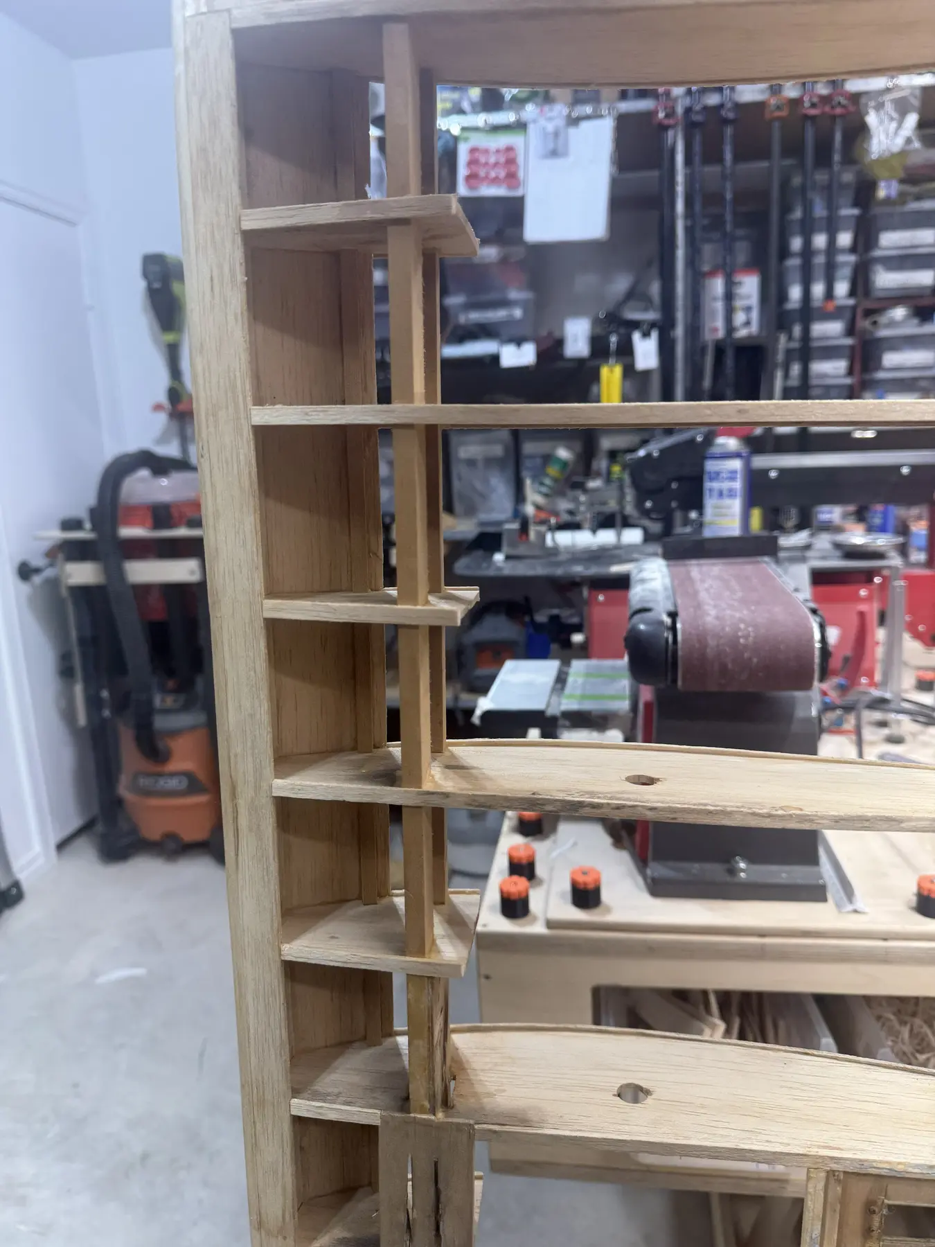
Each wing is treated as its own documented assembly. Spars, ribs, edges, root fittings, strut hardpoints, ailerons, hinges, servos, access hatches, wiring routes, and pitot installation are inspected and corrected before covering and final installation.
Wing teardown record
Overall and close views preserve the structure before repairs, hardware changes and covering preparation alter the wing record.
Current restoration milestone
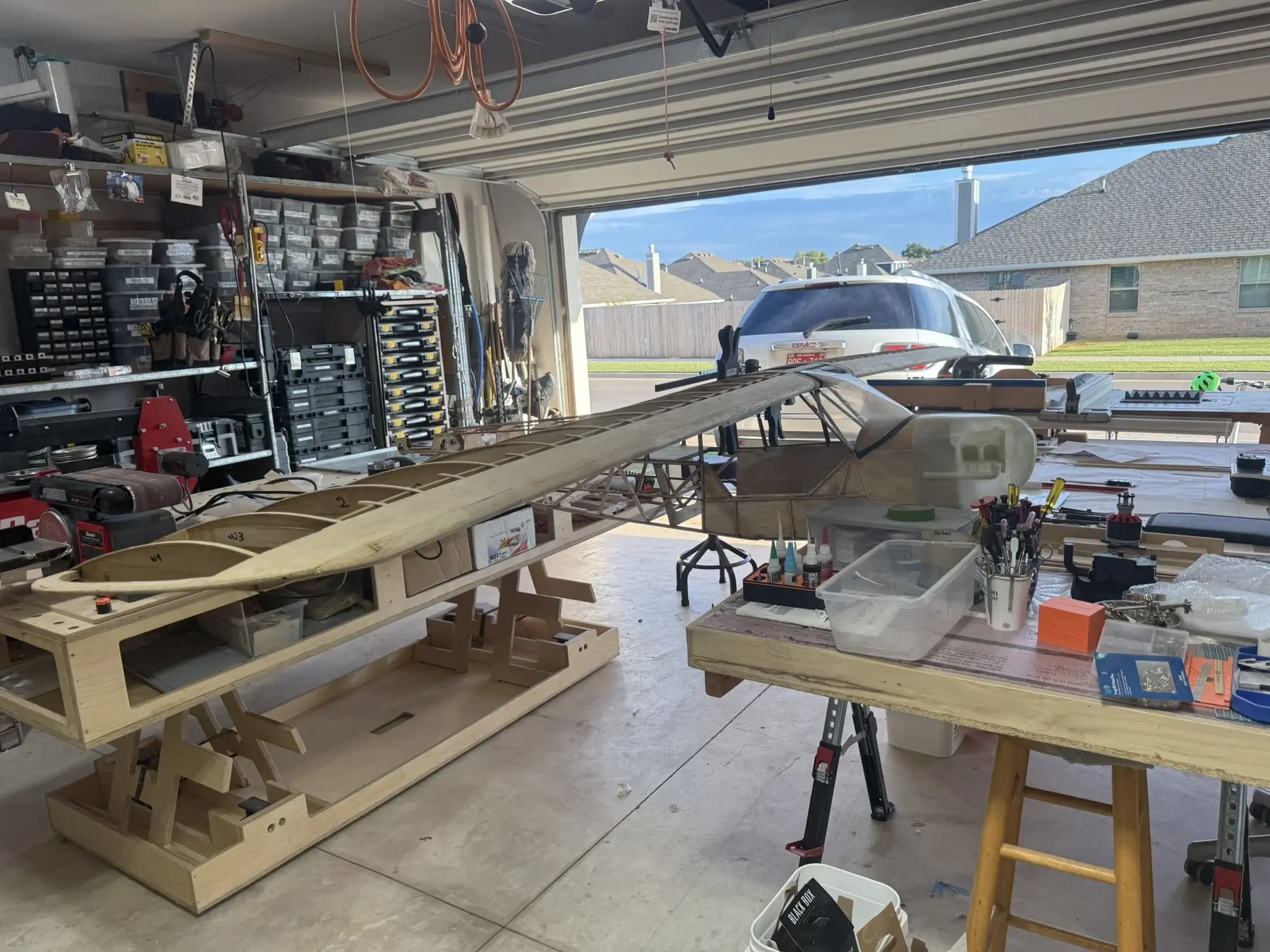
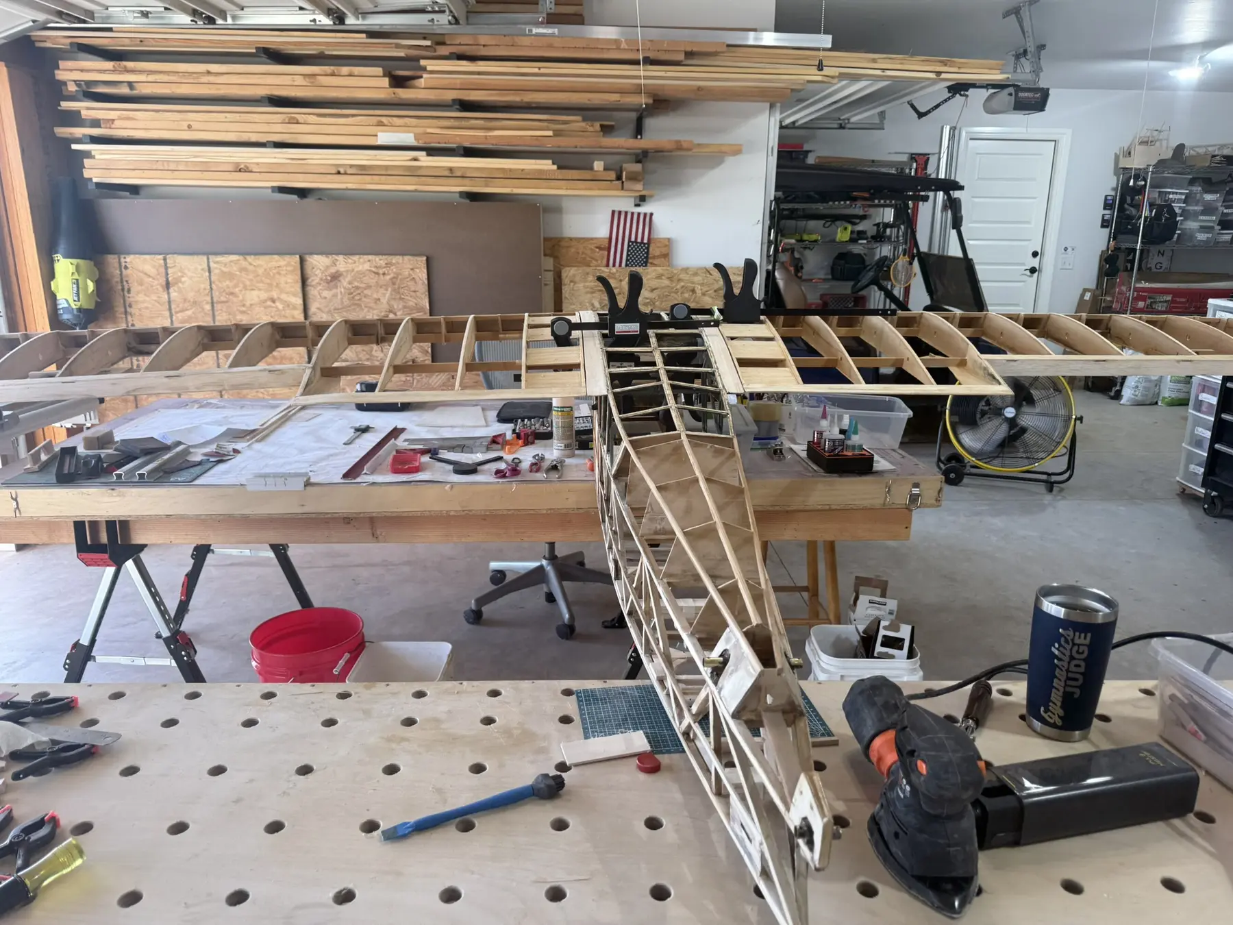
Temporarily returning both wings to the uncovered fuselage makes the aircraft's overall geometry visible again while inspection, alignment and restoration work remain active.
This is a meaningful assembly check, not a claim that the L-4 is complete or flight-ready. The exposed structure remains under review, and later covering, systems, controls, attachment and release work still have to be documented.
Separate Wing Records
The left wing and right wing receive separate inspection records, photographs, defect maps, measurements, hardware lists, and repair decisions. A condition found on one side prompts a check of the other, but it does not automatically establish the condition of both.
Each record follows the wing from the root to the tip and from the leading edge to the trailing edge, including the aileron, servo bay, strut fittings, attachment hardware, wiring, and covering boundaries.
Inspection Method
Overall views, root fittings, spars, rib bays, hardpoints, servo installations, hinges, horns, and every concealed repair.
Span, chord, sweep, incidence references, washout, aileron geometry, hinge spacing, strut locations, and root relationships.
Preserve, repair locally, rebuild, replace hardware, improve service access, or record for later monitoring.
Structural Inspection
The wing is inspected as a complete structure rather than as a collection of visible ribs. Main and rear spars, shear webs, root reinforcement, rib-to-spar joints, leading-edge sheeting, trailing-edge structure, wingtip framing, aileron bay boundaries, strut fittings, and attachment points must all transfer load into sound adjoining material.
Cracks, failed glue joints, crushed wood, enlarged holes, split plywood, loose blocks, hidden earlier repairs, and moisture or contamination are recorded before correction.
Root to Tip
Repair Standard
Sound original wing structure remains. Local defects are repaired only where the surrounding wood is straight, clean, and reliable. Compromised spars, root fittings, strut hardpoints, hinge supports, or servo mounts are rebuilt into sound adjoining structure rather than hidden beneath short doublers and excess adhesive.
All repair boundaries, materials, grain directions, joints, adhesives, and final inspections are recorded before the work is covered.
Ailerons
The ailerons are checked for straightness, twist, outline, trailing-edge condition, hinge reinforcement, control-horn structure, linkage geometry, clearance, and full travel. Left and right surfaces must match in neutral position, useful travel, hinge gap, and control response.
The Balsa USA configuration and the received aircraft establish the starting geometry. Any change to the hinge method must improve reliability and serviceability without casually changing the visible surface relationship or creating an unverified full-scale claim.
Straight, torsionally sound, free of hidden cracks, and ready to accept covering without introducing twist.
Straight, accurately positioned, reinforced in known structure, and free through the complete travel range.
Backed by sound structure, aligned to the hinge axis, and retained by inspectable hardware.
Hinge Decision
The kit is associated with a top-hinged aileron arrangement, and a bottom-hinge option has also existed for this airframe family. The restoration records the exact received configuration before choosing the final hinge installation.
Existing hinges are not reused merely because they are present. Hinge material, pin condition, alignment, withdrawal resistance, surrounding wood, and serviceability are evaluated. A piano-wire-style removable hinge system may be considered only if it can be installed accurately, retained positively, and documented as a restoration decision.
Servo Installations
Existing servo trays, mounting rails, hatches, linkages, pushrods, connectors, and wiring are inspected rather than assumed reusable. The final servo type is installed only in structure that is rigid, aligned, accessible, and capable of carrying repeated control loads without flexing the wing skin or hatch.
Control-System Testing
After installation, each aileron system is tested for neutral repeatability, full travel, free movement, linkage stiffness, current draw, fastener security, and structural flex. The inspection includes the servo mount, hatch, horn, pushrod, hinges, and surrounding wing structure.
Left and right ailerons are then compared for matched geometry and transmitter setup. Electronic matching does not substitute for correcting unequal mechanical installations.
Struts and Attachments
Strut brackets, internal blocks, plywood reinforcement, bolts, threaded inserts, clevises, jury-strut relationships, and fuselage attachment points are evaluated as one load-carrying system. A sound-looking external bracket is not enough if the internal block or surrounding spar structure is weak.
Loads spread into spars, ribs, webs, and reinforcement rather than ending at one small block.
Correct fit, visible retention, no elongated holes, and practical access for inspection and tightening.
Left and right strut lengths and attachment relationships support the documented wing alignment.
Wing Attachment
Wing-root attachment fittings and fasteners are inspected for wear, alignment, thread condition, crushing, and positive retention. The assembled wing must seat consistently without using fasteners to pull misaligned structure into position.
Field assembly should allow the wings, struts, wiring connectors, and pitot tubing to be connected in a controlled sequence without trapped wires, crossed hardware, or hidden partial engagement.
Wing Wiring
Servo wiring and any approved concealed provisions travel through protected routes that avoid sharp ribs, hinge hardware, strut fittings, moving linkages, and covering punctures. Passages use grommets, sleeves, secured guides, or lightweight conduit where needed.
Wing-root connectors are selected and mounted so they are keyed, strain-relieved, labeled, inspectable, and difficult to leave partially engaged. The connector system must support repeated field assembly without pulling directly on individual wires.
Future Provisions
Lightweight concealed conduit or spare pull paths may be installed where they provide reasonable future flexibility. Such provisions must be documented, secured, and kept proportionate to the actual likelihood of use.
The Normandy presentation does not require visible modern lighting. Concealed provisions preserve options without committing the finished aircraft to equipment that is not part of the approved historical appearance.
PAS70 ADV Pitot
The PAS70 ADV pitot system is integrated into the wing with a location and projection that support clean airflow while protecting the probe from routine handling and field assembly. The final position must be documented relative to the leading edge, wing surface, and nearby disturbances.
Rigidly mounted, accurately aligned, removable or protected for transport, and clear of propwash or local disturbance as practical.
Protected from kinks, crushing, sharp bends, heat, adhesive blockage, and damage during wing assembly.
Connections, tubing route, sensor location, leak checks, and calibration procedure remain accessible and documented.
Pitot Validation
The pitot system is checked for leaks, reversed connections, blocked tubing, unstable readings, and repeatability. Static bench response and field comparison are completed before airspeed callouts are treated as operational guidance.
Telemetry is an additional source of awareness. It does not replace visual flying, aircraft attitude, wind judgment, or a conservative flight-test program.
Alignment and Symmetry
Wing alignment is evaluated with both wings installed and the fuselage supported on the established datum. Root seating, incidence, tip position, sweep, dihedral, washout, strut geometry, and aileron neutral positions are compared left to right.
The objective is not to make disconnected measurements look equal. The objective is a straight, repeatable assembled aircraft whose geometry matches the Balsa USA design and the documented restoration configuration.
Load and Retention Testing
Before covering or final flight release, repaired structure, root attachments, strut hardpoints, servo mounts, hatches, hinges, horns, wiring, connectors, and pitot mounting are inspected and tested as an integrated system.
Testing is progressive and appropriate to the structure. The purpose is to reveal movement, looseness, flex, poor retention, or interference without creating damage through arbitrary overload.
Concealed Work Record
Spars, webs, ribs, root reinforcement, strut blocks, servo rails, hinge blocks, and repaired joints.
Wiring routes, grommets, connector mounts, tubing, pitot supports, and service loops.
Incidence, washout, symmetry, aileron neutral, hinge lines, horn positions, and final measurements.
Completion Standard
Both wings have continuous load paths, sound root and strut attachments, straight edges, and no unresolved defect.
Ailerons, hinges, servos, horns, linkages, and hatches move freely, retain securely, and match mechanically.
Wiring, root connectors, protected passages, pitot probe, tubing, and documentation are complete and serviceable.
Incidence, washout, sweep, dihedral, root seating, and aileron neutral are measured and repeatable.
Left and right records include photographs, defects, repairs, materials, hardware, measurements, and inspection results.
No unresolved structural, control, attachment, wiring, connector, pitot, or service-access issue remains.
Continue the Story
With the wings and ailerons documented and released, the restoration returns to the cabin. The molded floor, seats, instrument panel, side panels, controls, scale details, and concealed access to modern systems will be cleaned, repaired, reinforced, refinished, and installed around a serviceable equipment plan.
Return to the Journey