Preserve
Sound original structure
Retain straight, reliable longerons, uprights, cross-members, plywood, hardpoints, and builder-developed geometry.
L-4 Restoration · Chapter 04
The lower fuselage, belly access, landing-gear attachments, firewall, cockpit supports, propulsion-battery structure, and nose module must work as one continuous airframe. They cannot be rebuilt as unrelated hatches, trays, and brackets.
The goal is to restore dependable load paths and practical service access while preserving the aircraft's exterior shape and the documented configuration that made the model worth restoring.
On the restoration bench
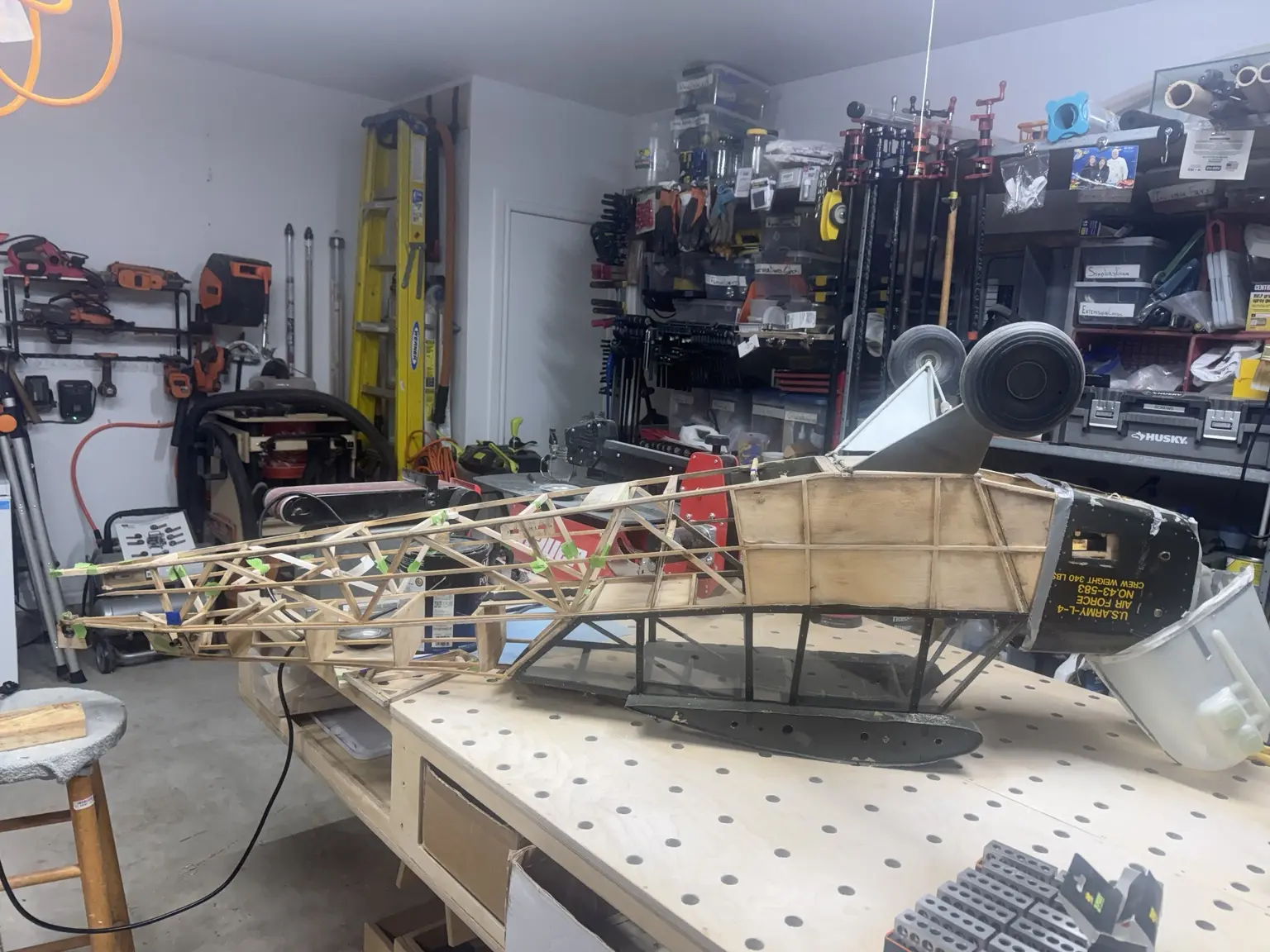
With the fuselage exposed and supported on the bench, longerons, cross-members, cockpit structure and the tail load path can be inspected as one connected airframe.
Existing Structure
The stripped fuselage is examined bay by bay. Lower longerons, uprights, diagonals, cross-members, plywood doublers, landing-gear supports, hatch rails, cockpit-floor supports, firewall joints, and earlier repairs are photographed and mapped before material is removed.
Weak structure may still preserve useful evidence: original dimensions, builder choices, hatch outlines, equipment locations, fastener patterns, and the relationship between the cabin, belly, landing gear, and nose.
Decision Framework
Retain straight, reliable longerons, uprights, cross-members, plywood, hardpoints, and builder-developed geometry.
Correct isolated cracks, loose joints, damaged gussets, or local crushing where the surrounding structure remains sound.
Replace weak hatch framing, failed gear supports, unreliable firewall joints, or structure that cannot be inspected or trusted.
Geometry and Datum
Reinforcing a twisted fuselage would only preserve the error. Before reconstruction begins, the fuselage is supported in a jig and checked against a centerline, level reference, firewall position, cabin geometry, wing relationship, landing-gear station, stabilizer platform, and tailpost.
Balsa USA plans control reconstructed geometry. The existing aircraft controls its received configuration and builder-specific relationships. Historical references guide visible full-scale appearance but do not replace the structural plans.
Continuous Structure
Landing loads must travel beyond a single plywood plate. Battery and equipment supports must transfer mass into cross-members and longerons. The firewall must connect into the fuselage sides, top, and lower structure without concentrating stress at one glue joint.
Splices and Joinery
Longeron and frame repairs use properly placed scarf joints, lap reinforcement, gussets, or replacement members extending into sound wood. New joints are located where they can be clamped, inspected, and supported by the surrounding bay geometry.
Adhesive follows the joint. Gaps are corrected by refitting the parts rather than being hidden beneath excess glue.
Belly Access
The useful locations of the existing belly openings are retained where practical, but weak rails, irregular edges, isolated tabs, and unsupported corners are rebuilt into complete framed openings with positive retention.
Each hatch sits inside a structural perimeter tied into cross-members, uprights, and longerons.
Latches, screws, pins, or captured fasteners resist vibration and airflow while remaining practical at the field.
Batteries, receivers, wiring, connectors, and fasteners remain reachable without dismantling unrelated structure.
Hatch size follows the maintenance task: the component must pass through, the hand must reach its fasteners, the connector must be visible, and the opening must not interrupt the load path that keeps the fuselage rigid.
Serviceability Under the Airframe
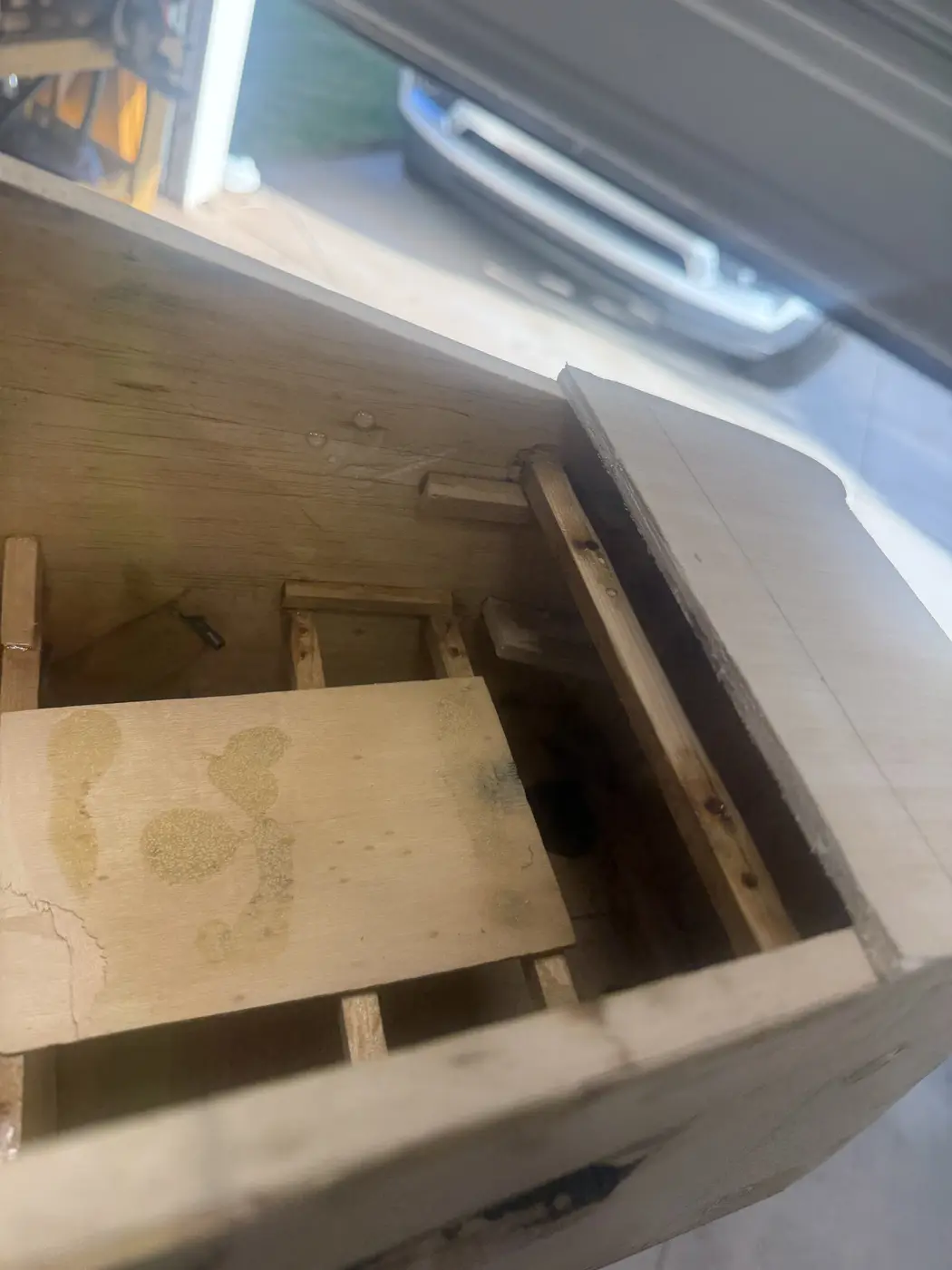
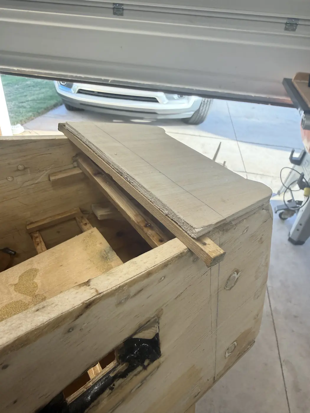
A large existing lower-fuselage opening is being retained and developed as a hinged service panel. Its final equipment assignment remains open, so the work is being treated as access structure rather than a confirmed battery hatch.
The adjacent fixed section is 3/16-inch plywood faced with approximately 1/16-inch balsa for a smooth finished exterior. A continuous piano hinge was considered for alignment and load distribution, but its exposed metal strip would be too visually intrusive on the finished L-4 belly.
The selected direction uses three concealed Robart #310 hinge points working through localized 1/2-inch-square basswood hardpoints. Only the panel seam should remain apparent from outside; the hinge hardware and reinforcement stay behind the surface.
Preserve serviceability while minimizing hardware that visually advertises itself as modern RC-model equipment.
The work remains at design selection, dry-fit and preparation. The hardpoints, seam clearance and common hinge axis must be established and checked before covering and permanent hinge installation.
See how the concealed hinge hardpoints were laid out in The Workshop →
Landing-Gear Structure
The landing gear is not judged only at the visible bolts. Gear plates, blocks, doublers, cross-members, side structure, lower longerons, fastener access, and surrounding glue joints are inspected as one system.
Crushed wood, enlarged holes, split plywood, loose blind nuts, contamination, and hidden cracking are corrected before new gear hardware is installed.
Firewall, Nose, and Cowl
The firewall position, thrust line, motor mount, cooling path, ESC location, propulsion-battery access, cowl mounting, and cockpit structure are developed together. The one-piece fiberglass Balsa USA-style J-3/L-4 cowl is the external reference, but it is not a structural substitute for a connected firewall and nose box.
The propulsion architecture is now locked at 12S using two 6S packs in series. The final motor, ESC, propeller, pack capacity, pack dimensions, connector selection, cooling details, tray position, and center-of-gravity location remain open until the complete airframe supplies reliable measurements and testing.
Why Plan Propulsion Early?
Locking the 12S architecture early establishes the need for two 6S packs, high-current series wiring, safe arming, substantial retention, cooling, and an independent control-power system. Leaving capacity, dimensions, and position open preserves the flexibility needed to balance the completed airplane without ballast or a compromised cockpit.
The fuselage must provide a practical route and support for two propulsion packs rather than discovering too late that the chosen hatch cannot pass them.
Battery supports and restraints must carry the mass of both packs through abrupt maneuvering and landing loads.
Fore-and-aft adjustment remains available until the cowl, motor, cockpit, covering, and final systems establish the real center of gravity.
Cowl Installation
The cowl is centered to the fuselage and spinner reference with consistent gaps and no forced distortion. Hardpoints are built into sound nose structure, and fasteners remain accessible without crushing the fiberglass.
The cowl can be removed for motor, ESC, wiring, cooling, and firewall inspection without disturbing completed airframe structure.
Propulsion Batteries and Equipment
The two 6S packs are installed as a matched series pair, but final capacity, dimensions, and exact location remain conditional on weight, balance, cooling, removal path, and connector access. Tray structure allows useful fore-and-aft adjustment.
Removable trays lock positively into the fuselage. Battery restraint works in every flight attitude and under an abrupt landing load. Connectors, series links, balance leads, and wiring remain protected from sharp edges, vibration, heat, and moving hardware.
Serviceable Installation
Receiver batteries, RB25S, receivers, telemetry, switches, connectors, propulsion components, and series wiring are concealed from normal exterior view while remaining inspectable and removable.
Concealed Work Record
Every splice, doubler, hardpoint, gear block, firewall joint, tray mount, wire passage, hatch latch, and structural repair is photographed before closure. Materials and measurements are recorded while they can still be verified.
The finished airplane should never require guesswork about what lies behind fabric, plywood, cockpit panels, or the fiberglass cowl.
Completion Standard
The fuselage remains straight and true, with the firewall, cabin, gear station, stabilizer platform, and tailpost in documented alignment.
Load paths continue through sound wood and properly fitted joints without unsupported hatches or isolated hardpoints.
Hatches, trays, cowl, batteries, electronics, connectors, and critical fasteners remain accessible for inspection and removal.
Continue the Story
With the fuselage datum established and the lower structure restored, the project can move into its first major physical reconstruction phase: rebuilding the rear fuselage relationships, stabilizer platform, tailpost, fin support, horizontal tail, elevators, vertical tail, and rudder.