Preserve
Documented layout
Retain usable molded pieces, established dimensions, sight lines, seat positions, panel location, door relationships, and builder-developed interior geometry.
L-4 Restoration · Chapter 07
The cockpit must look like part of a wartime L-4 while still working as the service center of a large electric RC aircraft.
The existing molded floor, seats, instrument panel, side panels, and trim are treated as reusable restoration assets. They are documented, repaired, reinforced, refinished, and returned to their established locations wherever practical—without trapping batteries, receivers, wiring, linkages, or inspection areas behind decorative parts.
Existing cockpit record
The original panel and cockpit arrangement establish the model-specific starting point. Wear, openings and mounting relationships are evidence—not reasons to substitute a generic interior.
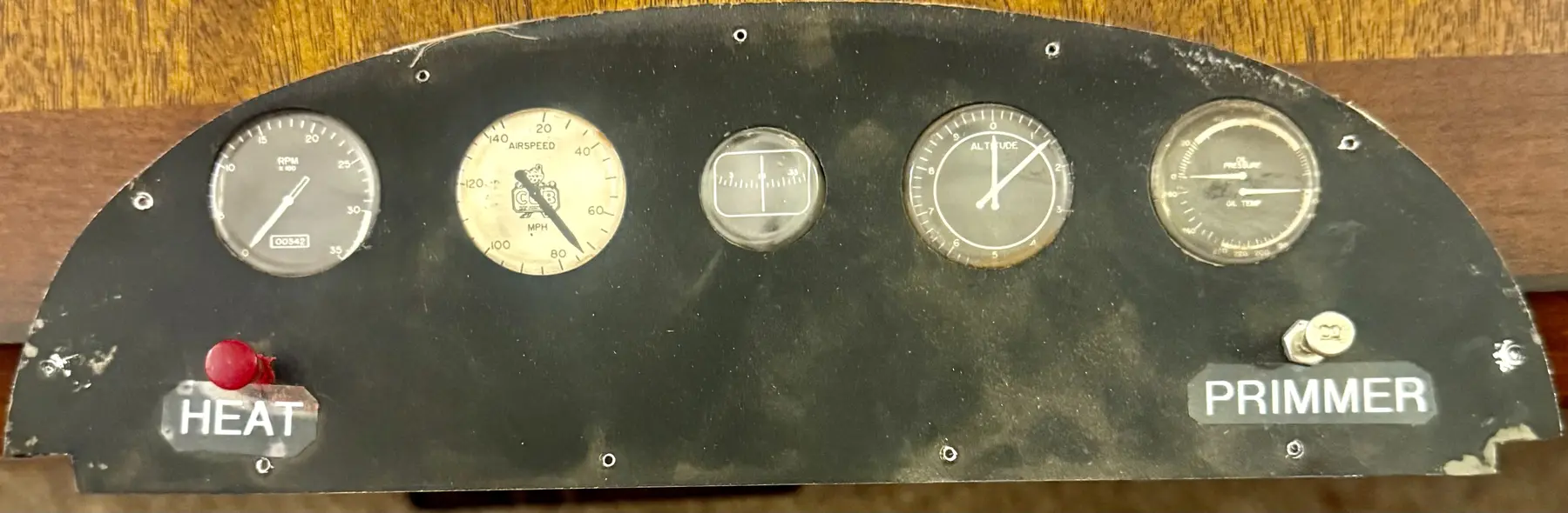
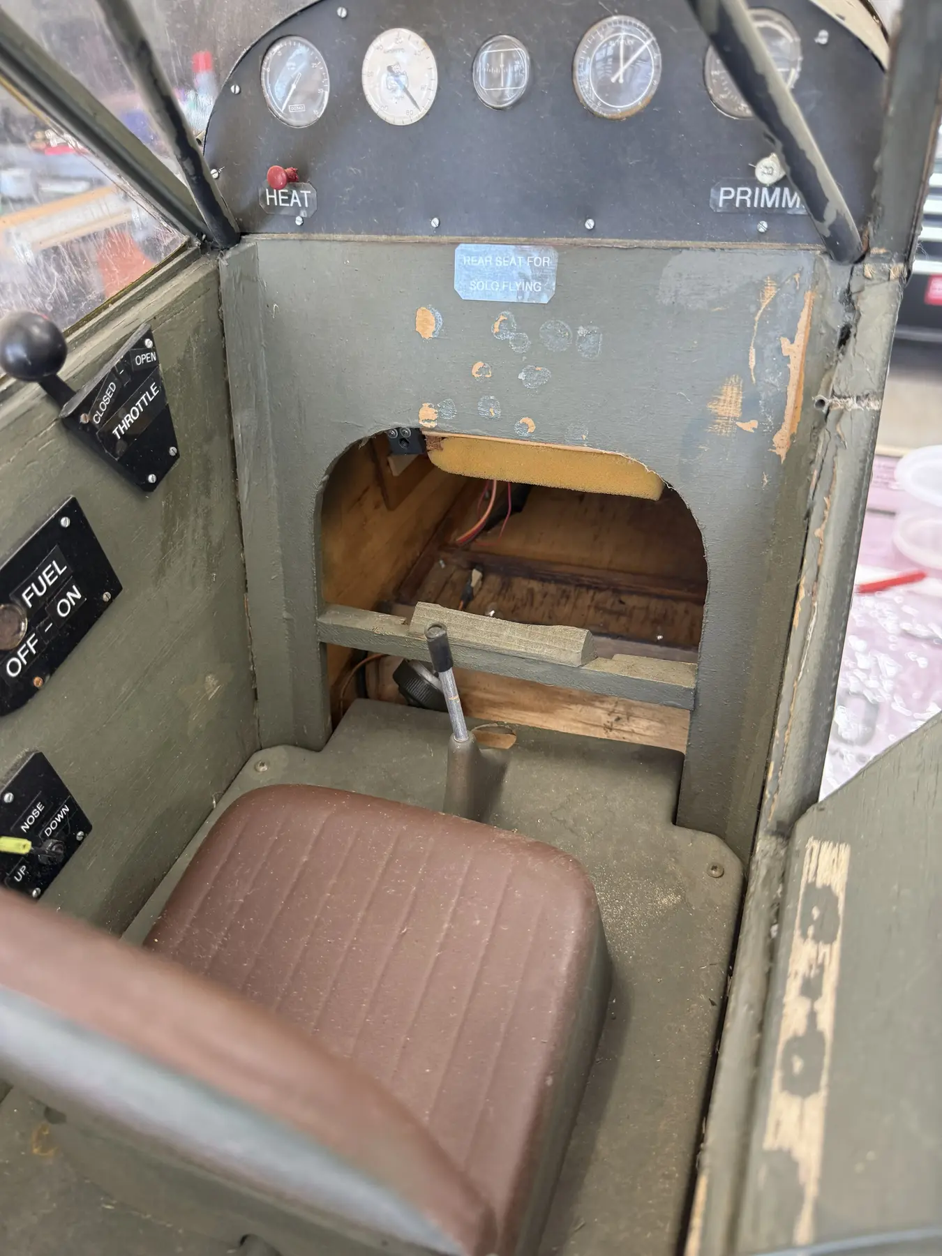
Existing Interior
Every preformed interior piece is photographed in place and separately. Its orientation, mounting points, clearances, neighboring parts, fasteners, finish, cracks, distortion, and relationship to the greenhouse and doors are recorded before repair or trimming begins.
The received arrangement establishes the model-specific baseline. Balsa USA references and reliable L-4 interior sources may clarify missing details, but they do not justify replacing a developed cockpit with an unrelated generic Cub interior.
Restoration Standard
The visible cockpit is treated like a carefully built stage set: convincing through the greenhouse, complete where the eye naturally looks, and deliberately removable where maintenance must occur.
Retain usable molded pieces, established dimensions, sight lines, seat positions, panel location, door relationships, and builder-developed interior geometry.
Clean, repair, reinforce, fill, sand, refinish, and remount the floor, seats, panel, side pieces, and trim without unnecessary replacement.
Add hidden retention, removable panels, labeled access, protected wiring, ventilation, and stronger attachment points where they improve safe operation.
Cleaning and Repair
Each part is cleaned with a method compatible with its material. Loose paint, contamination, failed adhesive, sharp edges, and cracks are removed or stabilized before refinishing. Reinforcement is placed only where needed around mounting points, thin corners, seat supports, or repaired cracks.
Large sheets of unnecessary fiberglass, heavy fillers, and permanent bonding are avoided. The goal is a durable interior that remains light enough to support the aircraft's center-of-gravity plan.
Visible Interior
The instrument panel is the principal visual focal point. Seats, floor, sidewalls, controls, and trim receive enough detail to make the cabin believable from normal viewing angles without turning the cockpit into a heavy full-depth museum model.
Instrument Panel
The panel is recorded before refinishing so its outline, mounting height, angle, openings, and relationship to the windshield remain known. Any replacement instrument faces, bezels, placards, switches, or printed details are based on supported L-4 references and the space available in the model.
The panel remains removable. It must not become a permanent wall blocking propulsion-battery access, wiring service loops, cooling paths, or inspection of the forward cabin and firewall area.
Seats and Floor
The floor and seats are restored as visible cockpit components, but they are also treated as access covers. A false-floor approach may conceal the RB25S, receivers, flight-control batteries, wiring, switches, or other systems beneath or behind removable sections.
Final equipment placement remains dependent on center-of-gravity validation, wire routing, ventilation, and the ability to remove components without dismantling unrelated structure. No interior detail is allowed to lock the aircraft into an unverified balance solution.
Sidewalls and Trim
Sidewall treatment is concentrated in areas visible through the windows and open doors. Lightweight sheet, formed plastic, printed parts, fabric, painted balsa, or retained molded pieces may be used where they create a convincing result without covering control exits, wiring, structural joints, or service fasteners.
Any panel hiding a component or linkage is removable and labeled in the restoration record. Decorative parts are never bonded over a known inspection point.
Scale Controls
Control columns, pedals, trim details, cables, handles, and other visible cockpit items may be represented where supported. They remain cosmetic unless specifically engineered as part of the operating system.
No scale control detail contacts servo arms, pushrods, pull-pull cables, switches, batteries, wiring, or removable panels.
Small details are secured against vibration and cannot fall into linkages or electrical equipment.
Model-specific decorative treatment is identified as a restoration decision unless supported as a verified full-scale L-4 feature.
Hidden Systems
The RB25S, receivers, two 2S LiFe flight-control batteries, switches, telemetry modules, connectors, and wiring are arranged behind or below removable cockpit pieces. The visible cabin remains clean, while every critical component remains reachable for inspection, testing, replacement, and configuration changes.
Propulsion remains electrically independent from the flight-control power system. Cockpit packaging must preserve that separation and must not allow a propulsion-system failure to remove control of the aircraft.
Equipment Layout
Interior pieces are repeatedly trial-fitted with representative equipment, wiring, batteries, control linkages, and greenhouse components before final finish.
Doors and Greenhouse
The restored cockpit is trial-fitted with the windshield, greenhouse framing, 0.040-inch clear PETG panels, doors, windows, latches, and retaining strips. Seats, panel edges, trim, handles, and removable equipment covers must not interfere with opening geometry or force the glazing out of alignment.
Interior finishing follows the structure-first, glazing-last sequence. Parts likely to scratch or load the PETG are fitted before final glazing installation.
Finishing
Colors, sheen, wear, placards, and instrument treatment support a clean operational U.S. Army L-4 rather than a heavily distressed display piece. The interior may show restrained service character, but exaggerated chipping, grime, or invented markings are avoided.
Every visible historical claim is separated from model-specific configuration and modern operational enhancement in the restoration record.
Installation Sequence
Document, clean, repair, reinforce, and dry-fit every existing interior piece.
Confirm equipment, battery, linkage, wiring, ventilation, and removal paths before final detailing.
Complete paint and details, install removable pieces, test access, and photograph the final concealed arrangement.
Documentation
Before each floor, seat, panel, or side piece is installed, photographs record the structure, electronics, batteries, connectors, wiring, control paths, fasteners, ventilation openings, and labels beneath it.
The record includes part identity, material, repair method, finish, mounting method, removal sequence, hidden equipment, and inspection result.
Completion Standard
The cockpit reads as a coherent wartime L-4 interior through the greenhouse without unsupported historical claims.
Seats, floor, panel, and side pieces can be removed without damage, and critical equipment remains inspectable.
No decorative item interferes with controls, wiring, batteries, cooling, doors, glazing, or flight-critical power separation.
Continue the Story
With the cockpit layout and removable service panels established, the restoration can document the RB25S, receiver arrangement, dual LiFe power, custom wiring, telemetry sensors, switches, connectors, failover testing, and final equipment map as a complete system.