Less vibration
Reduced vibration protects the greenhouse, clear PETG, cockpit details, wiring, sensors, restored joints and lightly built structure.

L-4 Restoration · Chapter 09
This Grasshopper is not being powered like a fast sport airplane. The planning direction is a 12S-class electric system built around low-speed pull, a large efficient propeller, cool routine operation and power in reserve — while the final matched motor, ESC, propeller, battery arrangement and settings remain open until the completed aircraft earns them.
Physical mockup
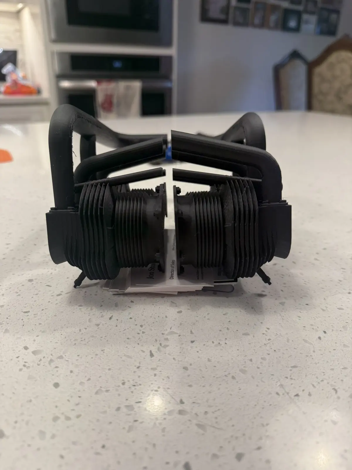
The dummy-engine and cowl mockup checks the visual opening, motor envelope, cooling path and service access before the final propulsion package is committed. See the prototype development in the 3D Print Lab →
Engineering Rabbit Holes
Each published story is a direct entry point: establish the sizing foundation, compare modeled systems, follow the battery-bay work, or see how the favored motor led to a mount concept.
 L-4 EngineeringMotor, ESC & Propeller SizingEstablish the propeller envelope, power target, voltage and component design range.Rabbit Hole · Go Deeper →L-4 EngineeringChoosing the L-4 Electric Power SystemCompare the BadAss and Scorpion finalists under the same modeled conditions.Rabbit Hole · Go Deeper →L-4 EngineeringThe Battery Bay Rabbit HoleFollow the mockups that proved geometry—not capacity—governs the two-pack installation.Rabbit Hole · Go Deeper →L-4 Engineering · NewThe Motor Was the Last Thing We ChoseFollow the favored motor from the plan-derived propeller envelope to a manufacturer-guided plywood motor-box concept.Rabbit Hole · Go Deeper →
The Central Idea
The L-4 is large, lightly loaded and intentionally slow. It needs useful thrust where the airplane actually flies: standing start, grass acceleration, climb, approach and go-around — not excess pitch speed.
The objective is not simply to install a powerful motor. It is to create the right kind of power: thrust where the aircraft uses it, at the speeds where a Cub actually flies.
Strong grass-field pull
Confident liftoff
Positive climb authority
Immediate go-around response
Comfortable partial-throttle cruise
Large-prop sound, not a high-RPM scream
Cool, dependable routine operation
Why Electric?
Electric propulsion fits the way this aircraft is being restored, displayed, serviced and tested. It reduces vibration and residue while allowing precise bench work and useful instrumentation.
Reduced vibration protects the greenhouse, clear PETG, cockpit details, wiring, sensors, restored joints and lightly built structure.
No fuel, oil or exhaust residue is deposited on the fabric, invasion stripes, clear panels, cowl interior or detailed cockpit.
Precise throttle response, repeatable bench testing, telemetry opportunities and a removable installation make system validation easier to document.
Electric is not automatically simple or maintenance-free. High-voltage battery handling, cooling, arming, connector condition, restraint and energy management remain disciplined parts of every flight.
Propulsive Efficiency
A large propeller turning at moderate RPM is naturally suited to static thrust and low-speed flight. The design target is useful pull, not wasted slipstream speed.
Static thrust matters when a large taildragger must begin moving and accelerate through grass.
Useful propwash over the elevator and rudder improves control while forward airspeed is still developing.
Climb and go-around performance matter at modest forward speed, where a Cub spends much of its useful flight envelope.
Large Propeller
Greater disk area lets the system influence more air each revolution without relying on excessive RPM. That can improve low-speed thrust, scale character and propwash authority when the motor, propeller, airframe and electrical load are properly matched.
Takeoff: strong static thrust through grass
Control: propwash reaches the tail before full airspeed
Sound: deeper, slower large-prop character
Constraint: ground clearance and current always govern
The rule is not “install the largest propeller possible.” It is to use the largest practical efficient propeller that clears the ground, matches the motor and delivers the required thrust without excessive current, vibration, temperature or structural load.
Low-Kv Motor Class
A lower-Kv motor on a higher-voltage system can suit a large propeller at moderate RPM, but Kv alone proves nothing. Winding, torque capability, shaft, bearings, mounting, cooling, propeller and operating point must work together.
Large-prop compatibility
Moderate operating RPM
Lower tip speed
Strong static thrust
Broad throttle response
Serviceable shaft and mounting
Why 12S-Class?
The current project direction is 12S-class, but the exact pack arrangement is intentionally open. For a given power level, higher voltage can reduce current and the associated voltage drop and resistive heating — only when the complete system is conservatively matched.
Lower current for equivalent power can reduce stress in wiring, connectors, solder joints, batteries and ESC conductors.
Higher voltage can support a low-Kv motor turning a large propeller without chasing extreme current.
An oversized propeller or poor cooling can overload a high-voltage system just as easily. Measured current and temperature decide.
Power in Reserve
The airplane should not need full throttle merely to cruise or remain airborne. Routine flight should use a comfortable portion of system capability, leaving additional thrust available when the aircraft genuinely needs it.
Grass takeoff
Initial climb
Go-around from low airspeed
Wind and turbulence
Approved added equipment
Partial-throttle normal cruise
Thermal Philosophy
Lower routine temperature is a design objective because heat is evidence of how hard the system is working. Thermal reserve should remain for takeoff, go-around, hot weather, taxi and repeated flights.
Cooler routine operation supports component life, consistent performance and lower battery and connector stress.
Peak temperature can occur after power is reduced. Post-run heat soak is part of the test record, not an afterthought.
The system is not considered healthy merely because it avoids an immediate thermal shutdown.
Scale Mission
The original liaison aircraft earned its value through short-field usefulness, slow-flight capability and dependable operation. The electric system should preserve that personality: authoritative takeoff, unstrained climb, easy cruise, smooth response and useful thrust at low airspeed.
Large propeller working
Moderate RPM
Broad throttle response
No prolonged full-throttle cruise
No overheated electronics
No high-RPM sport-airplane personality
Selection Status
The propulsion system is being developed as a complete combination of motor, ESC, propeller, batteries, cooling and airframe installation.
Separate Aircraft
The one-third-scale L-4 and one-quarter-scale Balsa USA J-3 are separate projects. Motor, ESC, propeller, batteries, settings and test results from the smaller Cub do not automatically transfer here.
Separate equipment list
Separate weight and balance
Separate propeller testing
Separate cooling study
Separate transmitter file
Separate as-flown record
Complete System
Motor, ESC, batteries, propeller, connectors, wire sizes, cooling, cowl, firewall and mounting structure are evaluated as one propulsion system. An excellent component can still be wrong for the installed combination.
Kv, torque, shaft, mounting, heat, weight and propeller compatibility.
Voltage/current margin, cooling, arming, logging/telemetry and removal path.
Diameter, pitch, balance, current load, ground clearance, vibration and appearance.
Capacity, current capability, mass, dimensions, retention, access and balance effect.
Defined inlet, guided airflow through heat sources and deliberate exit area.
Progressive runs, current/RPM/temperature measurement, inspection and documented release.
Motor / Firewall / Cowl Hold Point
Innov8tive Designs has recommended a reinforced plywood motor box bonded to the existing firewall as the current construction direction. Exact box geometry and installation remain open. Read the motor-box development →
Final hardware must fit the actual firewall, motor box, cowl, shaft line, spinner relationship and completed-aircraft balance. Thrust, torque, vibration and propeller loads must reach continuous structure rather than stop at a local plate.
Firewall condition and alignment
Thrust-line reference
Mounting pattern and fastener engagement
Wire and cooling clearance
Motor removal path
Post-run inspection access
Propeller and Clearance
Diameter and pitch are selected through measured electrical load and performance. Ground clearance must be checked with the completed landing gear, tires, aircraft weight, expected gear deflection, grass surface and realistic taxi attitudes.
A workshop measurement on an unloaded airframe is not treated as final proof.
Manufacturer, size, material, hub, balance, current, RPM, temperature, vibration and approval status belong in the test record.
Tire size, loaded deflection, surface, three-point and level attitudes all change the real margin.
Propulsion Batteries
Battery capacity, discharge capability, mass, dimensions, connector type, service history and location are evaluated together. The exact arrangement remains adjustable until the completed aircraft confirms its center-of-gravity needs.
Support must prevent forward, aft, vertical and lateral movement while remaining visible during preflight inspection.
Batteries need a deliberate removal path that does not require dismantling unrelated structure or damaging the cockpit.
Pack identity, measured mass, dimensions, connector condition and service history remain traceable.
Center of Gravity
Representative propulsion, cowl, cockpit, avionics, covering and scale-detail mass must be installed or accurately mocked before permanent trays are committed.
Component weight-and-arm estimate
Physical assembled-aircraft verification
Approved CG range
Battery-position marks
Retention recheck
Final as-flown weight and balance
ESC, Arming and Access
The final ESC must support the selected voltage and demonstrate adequate margin with the approved motor and propeller in the real installation. Published ratings are not a substitute for measured current, cooling and connector capability.
The system requires an unmistakable throttle cut and a deliberate physical arming sequence that does not put the operator in the propeller arc.
Settings, wiring, connectors and the ESC itself must remain inspectable and removable after the aircraft is finished.
Voltage/current rating, firmware/settings, wire/connector limits, cooling, arming method, measured temperature and approved prop combinations stay documented.
Cooling
Cowl openings alone do not guarantee cooling. The installation needs a pressure path that guides air through the motor, ESC and battery area before reaching a deliberate exit.
Baffles or ducts may be used where needed, but the result is proven by temperature data and post-run heat-soak observation rather than by appearance.
Defined inlet area
Air directed through motor
ESC in active airflow
Battery heat not trapped
Unobstructed hot-air exit
Post-run heat soak recorded
Telemetry and Warnings
Propulsion telemetry supports decisions, warnings and postflight diagnosis. It does not replace conservative battery planning or physical inspection.
Loaded voltage, current and capacity used can reveal real demand and changing battery behavior.
Temperature data can verify cooling and reveal abnormal heat or post-run heat soak after aircraft-specific sensors are actually allocated and installed.
RPM and recorded propeller data make tested combinations comparable rather than anecdotal.
Immediate voice alerts are reserved for conditions requiring action. Routine values remain available on demand rather than burying the warning that matters.
Progressive Test Program
No bench estimate or vendor rating becomes an as-flown claim. The system advances through deliberate, recorded steps.
Verify mounting, shaft line, clearance, restraint, connector routing, arming and cooling path before serious power runs.
Increase load in steps while recording current, voltage, RPM, temperature, vibration and post-run heat soak.
Confirm cooling, ground clearance, balance, restraint, interference, arming and service access in the completed aircraft.
Completion Standard
The propulsion system is successful when the aircraft has confident low-speed thrust, comfortable partial-throttle cruise, useful climb and go-around margin, conservative temperatures, safe arming, adequate ground clearance and a documented combination that can be inspected and repeated.
No unexplained current spikes
No abnormal vibration
No overheated motor, ESC, battery or connector
No marginal propeller clearance
No inaccessible arming or service point
No “as flown” claim before release testing